
Mind-Blowing Metal Forming Secret
45sThis clip introduces a revolutionary manufacturing process that challenges traditional metal stamping, sparking curiosity and awe.
▶ Play Clip"The title accurately reflects the video's content: it showcases a futuristic metalworking process that is indeed impressive and little-known."
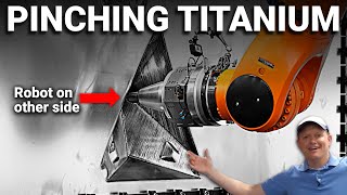
This video explores incremental sheet forming, also known as Roboforming, a manufacturing technique that uses two industrial robots to shape metal sheets without molds. The process allows for rapid prototyping and low-volume production, offering flexibility that traditional stamping cannot match.
Previous video covered progressive metal stamping, which uses coils of metal and large presses with dies for high-speed, high-volume production.
This video focuses on incremental sheet forming (Roboforming), which sacrifices speed and accuracy for the ability to iterate and create parts quickly, ideal for development and small batches.
Destin visits Machina Labs in LA, meeting CEO Ed (software background) and Boback (PhD in Materials Engineering) who lead technology partnerships.
Two end effectors (tools) pinch and deform a metal sheet, similar to a potter shaping clay. The process involves shear, stretching, and pinching to achieve complex geometries.
Roboforming is slower than stamping per part, but faster overall for small runs because no mold is needed. Break-even can be up to thousands of parts.
The technology is based on decades of research from professors and scientists worldwide, with patents from Japan, Europe, and Finland, but Machina Labs is the first to commercialize it.
They use KUKA robots (also compatible with Fanuc) and build their own control system. The robots are robot-agnostic.
A 2mm aluminum sheet is formed layer by layer, stretching and pinching to create a shape. The process is likened to a potter's wheel but not limited to round shapes.
Load cells on both robots measure forces (Z component and in-plane forces). One robot pushes, the other supports, localizing force between tips to reduce tension on the sheet.
By pinching with two end effectors, they locally deform metal past its yield strength, avoiding the 'tenting' effect that occurs when pushing from one side.
Robots have nominal trajectories but use force feedback to correct. One robot aims for position, the other for target pinch force. Robots deflect up to 6-7mm under 20,000N loads, requiring compensation.
Backlash in gear trains and joint deflection due to varying poses affect accuracy. The robot's stiffness depends on its configuration, similar to human arm strength at different angles.
Accuracy while forces are changing is critical. Joint angles must be adjusted (e.g., 60.1° instead of 60°) to account for deflection under load, incorporating force data into kinematics.
With 7 axes, there are infinite poses to reach a point. They optimize for stiffness to apply maximum force without deflection, choosing poses that minimize compliance.
The sheet's deflection varies based on where it is supported (boundary conditions). This affects accuracy and must be accounted for in the forming process.
After forming, the part is scanned to compare with the desired geometry. The software adjusts the toolpath to compensate for springback and deflection, iterating to improve accuracy.
End effectors can roll or be fixed. Rolling reduces friction. Minimum feature size is about 0.25-0.75 inches diameter. Tips can be perpendicular to the surface for complex shapes.
The robots can form on curved sections, not just planar slices. They use spiral paths to avoid seams and can chain multiple operations together.
Long-term goal is a 'robotic craftsman' that can pick up different tools (forming, scanning, trimming) automatically, changing end effectors via pneumatic and electrical connections.
After forming, the robot can pick up a trimming tool to cut the part. Tools are carbide with specialized coatings to prevent wear and part damage.
The software compensates for sheet deflection, springback, and tearing. Without it, parts would be inches off. The control system uses force data to stay accurate.
After forming, the robot scans the part, maps the scan to a trimming path, picks up a trimming end effector, and trims the part, leaving tabs for removal by technicians.
The technology can form titanium and high-temperature alloys (Inconel) for hypersonic aircraft skins, which are difficult to form traditionally. Examples include SR-71 and modern hypersonic vehicles.
A support skirt around the part provides rigidity. Steeper angles and deeper parts are more rigid. Shallow parts are harder to form. Wavy gussets add stiffness.
Material thickness varies: thickest in the plane, thinner on walls. Thinning is proportional to cosine of wall angle (or sin of draft angle) due to conservation of volume.
To avoid thinning, they use restriking: first form a cone, then push it out to a hemisphere, redistributing material for more uniform thickness.
Parts can be formed faster than they can be simulated on a computer, highlighting the efficiency of the process.
Incremental sheet forming (Roboforming) offers a flexible, mold-free method for shaping metal, ideal for prototyping and low-volume production. The technology, commercialized by Machina Labs, combines robotics, force control, and sophisticated software to achieve complex geometries in materials like titanium and aluminum.
What is the main advantage of incremental sheet forming over progressive stamping?
It allows for rapid iteration and part changes without needing a mold, making it ideal for prototyping and low-volume production.
00:52
What is the break-even point for Roboforming compared to stamping?
Up to thousands of parts, because no mold is needed.
03:29
How do the two robots work together in Roboforming?
One robot pushes the sheet, the other supports from the opposite side, pinching to localize force and reduce tension.
06:55
What is backlash in the context of robot arms?
Play between gear teeth when the robot changes direction, causing inaccuracies.
11:43
How much can the robots deflect under 20,000 Newtons of force?
6 to 7 millimeters.
10:17
What is the minimum feature size achievable with Roboforming?
About 0.25 to 0.75 inches diameter.
18:03
What is the 'robotic craftsman' concept?
A system that can automatically change tools (forming, scanning, trimming) to perform multiple operations like a human craftsman.
20:55
Why is software considered the 'secret sauce' of Roboforming?
It compensates for sheet deflection, springback, and tearing; without it, parts would be inches off.
23:37
What materials can Roboforming handle that are difficult for traditional forming?
Titanium and Inconel (high-temperature alloys) for hypersonic applications.
25:28
How does material thickness change during forming?
Thickness is proportional to the cosine of the wall angle; walls become thinner due to conservation of volume.
27:14
Rapid Iteration Advantage
Highlights the key benefit of Roboforming: speed of iteration for prototyping.
00:52Break-Even Point Surprise
Reveals that Roboforming can be faster than stamping for up to thousands of parts due to no mold.
03:29Pinching Technique
Explains the innovative dual-robot pinch method that localizes force.
06:55Robot Deflection Under Load
Quantifies the challenge of robot deflection (6-7mm) under high forces.
10:17Software as Secret Sauce
Emphasizes that software compensation is critical for accuracy.
23:37[00:10] Welcome back to Smarter Every Day. And you may recall in a previous video, we went to a progressive metal stamping factory, and this place was incredible.
[00:23] They took coils of metal and they rolled them through these big presses with dyes It's an incredible process. of time and skill to create these progressive stamping dyes.
[00:38] Now, we're not going to get the same level of accuracy or speed as we did in progressive metal stamping, but we are going to be able to iterate and create parts quickly, like change the part, which is an incredible asset when you're
[00:52] developing something or making a small number of parts. Smarter Every Day deep dive series into manufacturing, and we're going to learn The intricate details of how this process works blows my mind, and I've never seen
[01:08] this stuff on the Internet, and I think it's going to blow your mind as well. learn about incremental sheet forming, or as this company calls it, Roboforming. So out in L. A.
[01:23] And after a little bit of back and forth on the intercom because people are rightly suspicious about a guy walking up with cameras Oh, they opened it. Oh, nice.
[01:35] He's the one that reached out after seeing that I started a manufacturing series. And then we headed upstairs to the office portion of their lab/factory, where I met
[01:47] Ed is the CEO and has an interesting background in software, and Boback leads the technology partnerships and has a PhD in Materials Engineering. So my understanding is you guys have a way to create shaped metal by forming it by, I
[02:07] Let me just draw it right here. So you guys have a plane of metal and you bring two tools in and you can touch the metal like that.
[02:22] [E] I call them end effectors, but forming [D] Okay, got it. So when these two end effectors come in
[02:34] and they put force right here, you can deform the steel in there. assuming the position of this versus this matters.
[02:47] [D] Okay, and so you can do things that are really interesting. can think of, how a potter, you have a clay on your turning table, and the potter
[02:59] That's what we're trying to do with sheet, but it's a very strong sheet and it Deformation with the pinch, it can be shear, it can be stretching.
[03:12] part that you want. [D] So, you have access to more interesting geometries, but the trade-off is it takes a little more time to make the part. the part, but if you take into account the fact that you had to make a mold to make
[03:29] the part, then in a lot of cases, up to even thousands of parts were faster. [E] Because you can start making the part two hours after your design is done. Usually, the design of the mold is also
[03:42] Because the sheet has a spring back, you stamp bit, it comes off, it moves again. Your mold is usually different than your actual geometry. By the time you're going through those
[03:56] you get your part, you might be even faster just forming with us. obviously, we're slower than the stamping, stamping is a few, [D] This is great for development and low rate initial production.
[04:11] But you would be surprised where the break even point is. [D] Ed took us downstairs to see the robots. This is not like these guys invented this overnight.
[04:27] This is the result of decades of research by professors and scientists. history, you can see patents from Japan, Europe, Finland, all over the place. point where they can crack the code on how to do it.
[04:44] this, but nothing really commercialized out of those efforts. [E] We're running KUKAs at the moment.
[04:56] The robotic system is KUKAs, but we also can use Phanax. We are robot-agnostic. We pretty much basically build the whole control system for the robots from
[05:11] [D] It's like a dance. It's different than I thought. Sorry, I'm being rude. I'm Destin.
[05:26] Can I put a mic on you? Are you cool with that? This is incremental forming. It's a two-millimeter aluminum sheet and
[05:42] It's a lot like a potter's wheel, spinning like that. It doesn't have to be round.
[05:56] Layer by layer, we're stretching and pinching and pulling whatever shape I want here out of this metal. [D] The triangle here is coming out of plane. [M] That's right.
[06:10] [D] Which means this one over here, are there any optical lockouts I need to be. [M] Just try not to get between the robot and the sheet. This one is pushing. [M] That's right.
[06:24] [M] Yeah, there's load cells on both robots, This is the forces that both robots are feeling right now. [M] Yeah, there's the Z component, the
[06:41] [D] It's pretty easy to understand the force is pushing into the plate, but the in-plane forces are the side-to-side forces as the thing moves around. [M] There's robot number one here is the one that's pushing, and then robot number two
[06:55] What you could do is you could do this process with just one robot, and you could [D] But the boundary conditions. Does it work? So what we're doing by having a support robot on the other side is you pinch, and
[07:11] so you localize all the force just between the tips, which reduces tension on the [D] That's amazing. Okay, what Mark just said was crazy, and I This is just fabric on a sewing frame. Check this out.
[07:27] If you push against this thing, it's going to tent out, right? This doesn't behave like the metal does, but it's going to deform out there. Now, when people work with metal, they use something called breaking in order to
[07:41] locally deform the metal past its yield strength, basically. What they're having to do in this case is because they're poking on one side, if you were to push so hard that you deform it, it would tent out.
[07:55] So they're locally doing it by putting two end defectors right next to each other and That's really hard to do when you have So what they're talking about is wild because when you break metal, you normally
[08:13] have a rigid datum, and you bend over a corner, they don't have a rigid datum. They're moving things around, which makes this complicated. I would expect a positive force or compressive force on that one.
[08:27] one position, would you just hold the robot here until it feels forced from the other side so that you know that you are actually pinching? Because should I talk about all this stuff?
[08:41] [D] Well, should I let him do it since it's ultimately his authority? [E] No, I think Mark knows, yes. Go ahead. both of these robots where we can plan their nominal trajectory.
[08:57] They feel the forces, and we use that to [M] Yeah. One of them is correcting for its own
[09:11] The other one is trying to hit a target pinch force that we set. supposed to get to a certain point in space, and the second robot is supposed to
[09:23] push at a certain force required to bend the metal. force, the robot itself starts to bend, so you have to accommodate for that.
[09:35] The envelope is 12 foot by five foot. Getting two industrial robots to be very accurate in this envelope is one task that we have to do through a lot of calibration and proper kinematics.
[09:48] But then the moment they start touching sheet, the sheet will resist them. You can imagine every joint slightly deflects. There are controls and mechanisms that basically compensate for that deflection
[10:03] Sometimes, depending on what sheet we are forming, it can be like 20,000 Newtons of force that you're applying. on a very small end effector on the forming side.
[10:17] Under those loads, robots sometimes deflect 6, 7 millimeters. millimeters or half a millimeter, so we have to adjust for that. There's a control loop that uses the force data, some of the other data to constantly
[10:32] figure out how it can stay accurate and pitch the sheet the right way. Is there a robot around this corner? Okay. If I understand what you just said,
[10:46] there's many ways to arrive at this point with this linkage. If I arrive at this point and apply 5,000 pounds in that direction, I'm going to get a certain radial deflection here.
[11:02] You have to also determine how you get [D] When you have a robot like this with a lot of different joints, you can be in one It's funny, but you see what I'm trying to say.
[11:18] If you've got 5,000 pounds of force that's in line with this first actuator here, But if you think about that second actuator, the offset between the force and
[11:31] the actuator will determine the amount of torque that that thing has to resist. And the same thing applies to that third actuator down here, and all of those forces eventually get transmitted down to the base of the robot.
[11:43] And if you were to zoom in, you would find that these gear trains are imperfect. were to stop and reverse and go the other direction, you would find that there's
[11:56] play between the gear teeth, and that causes something called backlash. Watch the robot draw this shape. direction at different moments along the Polygon.
[12:11] happening in the robot arm as it changes directions. Backslash is also something you have to take into account with linear actuators
[12:24] like this screw system here that's moving this big robot back and forth. you've got to take into account backlash there as well. the actuators themselves, we also have issues,
[12:37] tried to drill something in really high like this and your arm is all weak because of where you're at, but if you're up here and you really put your power behind it and you line everything up, you don't deflect as much and you get more strength
[12:52] Actuator movements. [E] There's two types of accuracy. while the forces are changing on the robot.
[13:07] okay, the joint A1 not only need to be at 60 degrees, they need to be at 60.1 or 60.2 degrees, depending if at the end, the factor is facing a 5,000-pound force, and including that into the kinematic calculation.
[13:24] It's a fun thing that our robotic team is working on. [D] If this is at zero degrees and I'm pushing into that, are there many different ways Because we have seven axes,
[13:39] there's unlimited ways to get to that point with different poses. Do you pick a few things and say, This always has to be here, You can just choose, randomly choose, or you can optimize, for example, for a
[13:56] You say, Okay, move the robot and the rails so the joints are the most stiffest combination to apply the most amount of force without deflection. You can part of your kinematics, you can figure out what exactly you want to do.
[14:13] [D] This episode of Smart Every Day is sponsored by NordVPN, which is a virtual You can get a ridiculous deal right now with Nord if you go to NordVPN.
[14:29] And then the reason you don't see it on this piece of aluminum right here is because we're about to manufacture that while I tell you more about NordVPN. use NordVPN is to mask what I'm searching on the Internet.
[14:45] over my shoulder when I'm trying to learn about things I don't know a lot about. Maybe they have something to do with health things. virtual private network to maintain your privacy online.
[14:58] You can even connect to the internet from different places in the world. There's over 5400 servers you can choose from in 60 countries. This protects from malicious sites, downloads, trackers, and malicious ads.
[15:13] the Internet for six different devices, so you can use it on all the things. You can see the URL is starting to come to life here, NordVPN. plan specifically, and you get four months free.
[15:29] It's risk-free because Nord gives you a 30-day money-back guarantee. They don't collect, track, or share your private data. Smarter every day by supporting the sponsor, you can go to NordVPN.
[15:46] Thanks for sticking around for that build. You know what's going on here, and I'm Okay, that's just all the robot.
[15:58] If we have a piece of metal and we push on it, it's going to deflect, right? on it, it's going to deflect in the middle, right? What happens if we're holding it here and here and we have to push on it down here?
[16:13] You're going to get a different deflection curve all along the way. Piece of fabric here, right? Think about that. That's what's called an indeterminate deflection beam.
[16:26] It's way different. So if I were to push up in the middle of this thing, I were to get a deflection right there in the middle, it's going to
[16:39] towards the edge than it is towards the middle. It's hard to see this, but this is also something that has to be taken into What do you call it when if I were to take
[16:53] a sheet and I were to touch in the middle, I would get more deflection than the edge? [E] I think we call it boundary condition effects. Boundary condition affects the accuracy of the parts that you get.
[17:07] You can imagine you form a part, you can then scan it. [E] To figure out, yes, exact quality, or to just figure out what it formed. Then it will be like, Okay, I formed this.
[17:22] in some areas and pushed less in some others. It can manually iterate on that or keep generating data and then later create a the sheet, you need to actually form a completely different part.
[17:38] the right part with all these things we talked about. Just like injection molding or something. Because it's actually rolling, isn't it? [E] Yes.
[17:50] There are other ones that we have that roll in different ways. [E] Yes, exactly. Depending what effect you want to get out
[18:03] If it's a sharp crease, different... Okay. [E] But that detects the smallest feature that you can do. We've done a quarter-an-inch diameter or some very fine detail feature.
[18:16] Three-quarters-in-inch diameter? Yeah. I can't predict where it's going. Yeah, it's rolling along the pointing axis, I'll say.
[18:34] changes wall angle where the tip goes in and out. Right here at the bottom of the part, [D] Oh, so I see.
[18:46] [M] Yeah, this wall is steeper than this wall, and now it gets steeper again. keep the tips perpendicular to the surface that you're forming.
[18:59] Even though it looks like it's a 2D operation [M] They're planar slices, but the tips move [D] Oh, really?
[19:13] [E] Let me show you some of the parts too that are non-planer. You're forming on a curved section. Now. you're forming from a section that's already have forming in it.
[19:26] Now your robot is actually going into a non-planer surface to deform and make. [M] Yeah, we're doing the face and then this This whole thing is about 90 minutes.
[19:41] This one's actually a spiral rather than layers. [M] It's a 1 millimeter pitch, but it's just a spiral the whole way.
[19:53] Then all of these are actually chained together as a single operation. Slowing down or something. going to do one plane and then just move in the Z-axis and do more and more planes.
[20:09] Right here, there's a bit of a seam, if But if I do a spiral, then you won't find that on this part. [M] This one is just planer slices.
[20:24] [D] Oh, I see. [M] The other one there is pathed as a spiral. It's just a continuous going a. Little bit deeper. [M] I guess a little bit because you don't have to turn around.
[20:39] [D] Can you tell me about the end effector here? [E] Yeah, so the.. [D] Can I stand here? [E] Yeah, of course. even though we are doing sheet forming, really our long-term goal is to build what
[20:55] we call a robotic craftsman, a system that works like a craftsman. You can pick up a forming tool, form it, drop the forming tool, pick up a scanner, You can see there's a spinel there.
[21:09] [D] Is that an ER-20 or something? [E] Yeah. The idea is you can easily change it. drop a tool, pick up another tool, and just move on to the next operation.
[21:24] really working like a craftsman that can pick up tools and do different things. [D] Okay, so you're not pushing like, Oh, you're applying electrical contacts, and then you have the mill here.
[21:37] Once you pick up, it automatically connects through the electrical contacts. They can drop this, pick up the forming in the factor, go back to forming. [D] You have indexing pins to align it, and you also align on the plane.
[21:52] Then what's going on here? through air pressure, they lock into the tool. Once it picks up the slave, this thing basically, through air pressure, come out
[22:06] [D] Oh That's amazing. These are pneumatic connections and these are electrical connections. [E] Right now, we do mostly forming and trimming.
[22:19] You can see that tool is in a spindle that allows us to cut the parts after we form them. That one doesn't have the final end effector that goes into it.
[22:34] The one next to it, it does. [D] This one. [E] You can see that the end effector is right in there. [D] Your tools, are they carbide or is that too brittle?
[22:46] Right now, most of our tools are the base of it is carbide. That coating is slightly more complicated.
[22:58] That's a coating that basically allows us to do many parts form many parts without basically destroying the part or destroying the tool.
[23:11] That's the end effector is pretty simple. This is one of the design that we're working at the moment. [D] That's the secret sauce?
[23:24] Took a while. 7:00 PM, running to UPS, get this out. [Destin laughing] really also comes down to the software pieces.
[23:37] run them in just get the geometry, slice it in water lines and start forming it, the final part is going to be inches off of what you actually want.
[23:51] We talked a little bit about deflection of the sheet, spring back of the geometry itself, and then the fact that it can also tear. amount of compression force between the tips, you might tear the sheet.
[24:08] We get to the fracture limit and we tear the sheet. part that's going to be very close to your final geometry and not inches off.
[24:21] That's, I think, where the real secret sauce is, the software piece. [D] When you get done with this thing, you're going to have a fully formed sheet. It'll be done. How do you get it,
[24:34] after it's forming it, scans it, and then maps the scan to the trimming path. the best way, picks up a trimming end effector and trims the part out.
[24:50] then technicians come in and cut the few tabs and take it out. so that the part is.. [D] Before you remove it. Then you leave few tabs in and then you cut those tabs and clean those tabs up.
[25:04] [D] If you had titanium, back in the day when they were building I saw the glimmer in your eye. [E] To this day, I don't think they can easily work titanium.
[25:16] We figured out how to machine it, but still forming it is very tough. [D] But, in theory.
[25:28] Could you use this technology to form it and then go in and cut the rivet holes? [E] I think those are the areas that you're the most excited. I think, for example, for Hypersonic, you
[25:42] said SR-71, but all the Hypersonic applications as the focus of attention a lot now with some of our customers, they have a very hard time forming skin of these aircrafts out of high temperature alloys, titanium, inconel.
[25:57] [D] Is this titanium? [B] This is titanium. customer cut out, but you can see the rest of the sheet. [D] This is all not part of the part, but this
[26:09] [E] We create enough stiffness around the part [D] Got it. That makes sense.
[26:22] Because if I'm pushing right here, so steeper angles give more rigid parts. The deeper it is, it becomes rigid more rigid.
[26:34] The deeper it gets, also you are more rigid because you have to overcome a If you want to do a very shallow part, it just doesn't work.
[26:46] Once you go further deep, then you create more rigidity. elasticity and get to plastic regime faster. The rigidity of this support skirt around
[27:02] the part is key, and a keen observer will notice that in a lot of these parts laying around the shop, it's not just a flat crease with the back plane, it's actually a wavy gusset because that's a more rigid structure.
[27:14] here, is the material the thickest it will ever be right here in the plane? Thinner here. Is that true? is that conservation of volume, right?
[27:31] the cosine of your wall angle or sin of your draft angle In the part. [D] Ed took me to a whiteboard and he The quickest way to explain restriking is if I want to make a hemisphere in one
[27:50] shot, it'll make the side walls right around the outside diameter too thin. make a cone and you push that cone out, then you'll have more material, so you'll If you want to learn more about how this works and a ton of different things that
[28:05] we didn't talk about in this video, I've got a lot of that stuff on this second right into the weeds with us and understand all these really cool concepts. [E] You can form parts faster than you could simulate it on the computer, right?
[28:23] [E] Yes. [D] A huge thanks to the folks at Machina Labs for showing us this stuff, incremental It's a really cool thing, and I'm grateful
[28:37] that they helped us continue the smarter everyday manufacturing series. manufacturing series, I have an email list. Com. There's a link to the email list there.
[28:50] Finally, I want to say thank you to the patrons of Smarter Every Day. It's a lot of work, and the patrons make it possible. This community of people is the driving force behind me hitting schedules and
[29:06] I'm so grateful for everybody that If you would like to consider that, I'd be grateful. You can check that out at
[29:19] And we've had a good vibe going over at patreon. If you'd like to check that out, I'd be excited about that. I hope you enjoyed this, the next video in the manufacturing series.
[29:33] more information over on the second channel in the long video. You're getting smarter every day. Have a good one. Bye.
⚡ Saved you 0h 29m reading this? Transcribe any YouTube video for free — no signup needed.