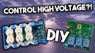

This DIY high voltage project is on you
30sHigh voltage safety disclaimers are highly shareable because they scare viewers into respecting dangerous DIY electronics.
▶ Play Clip"Delivers exactly what the title promises: a thorough, hands-on hardware assembly guide with no bait and plenty of substance."
Matt from MKS presents the hardware assembly portion of a four-part series on building a DIY smart power strip. This video walks through the complete bill of materials, required tools, PCB soldering, outlet wiring, and enclosure assembly, with a strong emphasis on high-voltage safety. The finished device uses an ESP8266 to independently control three outlets, and the software side will be covered in the next video.
Matt introduces a four-part DIY smart power strip series: demo, hardware, software, and deploy. This is the second video, focused on hardware assembly.
The smart power strip lets you turn on and off anything plugged into three outlets. A giveaway for a power strip kit is also announced and is international.
The PCB for this project was made by PCBWay. Viewers can use the on-screen code to get $5 off at PCBWay.
Key parts include an ESP8266, three 1N4001 diodes, five 2-pin terminals, a 4-pin female header, a 3-pin male header, a 2-pin jumper, three 5V relays, three 2N2222 transistors, 330Ω and 3.3KΩ resistors, a USB connector, 22AWG and 14AWG wires, push-in connectors, spade connectors, a 5V power supply, outlet box and faceplate.
Tools include a soldering iron, hot glue gun, wire strippers, wire cutters, Phillips and flathead screwdrivers, solder, flux, helping hands, PCB holder, and multimeter. Optional tools are a solder fume fan and steel wire tip cleaner.
The device controls high voltage, so the creator warns that you must be very careful and that you are responsible for your own work.
Install three 5V relays into positions Relay 1, Relay 2, and Relay 3. Align the pins, push down to seat, then solder after applying flux.
Insert 2-pin terminals into J1-J5 using wall tack to hold them in place. Then solder 1N4001 diodes into D1-D3, matching the silver line on the diode with the line on the PCB.
R1-R3 get 330Ω resistors and R4-R6 get 3.3KΩ resistors. Use a multimeter set to ohms to identify the resistor values.
Install 2N2222 transistors into Q1-Q3 by matching the curved side to the PCB. Then add the 3-pin male header (J7), 4-pin female header (J6), and 5V-to-3.3V converter (U2), aligning VIN and ground.
Set the 2-pin jumper to 'program' unless the board is pre-flashed. Solder the ESP8266 into U1 using flux and an SMD soldering technique: heat the pad and feed solder from the other side.
Strip the 2-conductor 22AWG cable, separate the pull-string, solder the wires to the USB connector (black on one side, red on the other), assemble the housing, and add hot glue for strain relief.
For each outlet, strip one-foot 14AWG black, white, and green wires. Bend hooks around a screwdriver, then attach black to the hot screw, white to the white screw, and green to the green screw. Tighten unused screws too.
Connect the outlet black wires to the PCB plus terminals and white wires to the minus terminals without mixing them up. Combine all green wires in a 4-port push-in connector, and connect the main 14AWG power cable.
Mains power feeds the relays and a 5V adapter. The ESP8266 controls transistors that switch each 5V relay, allowing each outlet to be turned on or off independently.
The hardware build is complete after soldering the PCB, wiring the outlets, and assembling the enclosure. The next step is flashing the ESP8266 and installing the faceplate, which will be covered in the software video.
PCBWay
service
Lowe's
service
Soldering iron
tool
Hot glue gun
tool
Wire strippers
tool
Wire cutters
tool
Phillips screwdriver
tool
Flathead screwdriver
tool
Solder
tool
Flux
tool
Helping hands
tool
PCB holder
tool
Multimeter
tool
Steel wire tip cleaner
tool
Solder fume fan
tool
MK Smart Shop
link
MK Smart Discord
link
Matt (MKS)
person
What microcontroller acts as the brain of the DIY smart power strip?
The ESP8266.
01:38
How many 5V relays are used, and where do they go on the PCB?
Three relays, placed in positions Relay 1, Relay 2, and Relay 3.
04:46
How do you distinguish a 330Ω resistor from a 3.3KΩ resistor during assembly?
Use a multimeter set to the ohms range and test each resistor.
09:45
Which resistor values go into R1-R3 and R4-R6?
R1-R3 get 330Ω and R4-R6 get 3.3KΩ.
09:32
Why are 2N2222 transistors needed in the circuit?
They switch the 5V relays on and off because the ESP8266 uses 3.3V logic, not 5V.
36:35
When should the 2-pin jumper be set to 'program' versus 'run'?
Set it to 'program' to flash new firmware; set it to 'run' if the board is pre-flashed.
12:44
What safety warning does the creator give about this project?
The device controls high voltage, so you must be very careful and are responsible for your actions.
04:22
How should the 1N4001 diodes be aligned on the PCB?
Match the silver line on the diode with the line printed on the PCB.
08:25
What is the power source for the PCB, and how is it connected?
A 5V power adapter connected with female spade connectors.
33:59
High-voltage responsibility
The creator explicitly warns that mains voltage is involved and that builders are responsible for their own safety, setting the right tone for a DIY electrical project.
04:22Multimeter beats guesswork
Using an ohmmeter to identify 330Ω vs 3.3KΩ resistors is a simple, practical technique that prevents costly mistakes.
09:05SMD soldering the ESP8266
The explanation of fluxing pads and feeding solder while heating only one side is a core skill for anyone assembling boards with surface-mount modules.
12:593.3V logic controlling 5V relays
The whole design hinges on transistors bridging the ESP8266's 3.3V logic and the relays' 5V coils — a reusable concept in embedded projects.
35:40[00:03] Matt here from MKS - calm and in this video we're gonna be doing my favorite video we're gonna be doing my favorite thing wiring the smart power strip is a
[00:28] cheap DIY smart home device that I show you how to make which means there will you how to make which means there will be four videos demo hardware software and deploy this is the second video the hardware video where I'm going to show
[00:41] you all the parts needed to make this and how to assemble it together the smart power strip is basically a device where you can turn on and off anything you plug into the three outlets from now on every device I show you guys how to
[00:53] make I'll be giving away so if you want a chance to win a power strip kit then click the link to the giveaway in the description it is very easy to enter and you have a good chance and it is international something else that is
[01:08] international is pcp a PCBU a is a company that specializes in PCB prototyping PCB assembly and SMD centel in this video we will be using a PCB that was made by PCB way as you can see the PCB is high quality and very nicely
[01:22] made if you use the cash code on the screen you can get five dollars on PCB so what other parts does this device used besides the PCB well you're going to need an esp8266 this is the brains of the device one and four zero zero one
[01:38] diodes three of them five two pin terminals one four pin female header one 3 pin male header one two pin jumper 3 5 volt relays three two and two - two transistors three 300 ohm resistors 33.3
[01:53] transistors three 300 ohm resistors 33.3 km/h b connector six inches of two conductor 22 gauge cable three one foot green 14 gauge cable for one foot black
[02:06] green 14 gauge cable for one foot black 14 gauge cables one six inch black 14 gauge cable for one foot white four gage cables 1/6 inch white 14 gauge cable 1/4 pushin connector 2 3 port push and connectors 2 female Spade connectors
[02:22] 1 5 volt power supply 1/4 gang electrical box 1 faceplate in screws this is a custom faceplate so you can buy the individual pieces and then you put them together and then they make one big custom faceplate I picked this up at
[02:36] my local Lowe's and you're also going to need the screws for the faceplate 3 need the screws for the faceplate 3 outlets and 1 14 gauge power cord this going to be cutting off the end and then connecting it to the power strip now
[02:49] that the components are out of the way what tools are we going to use you're going to need a soldering iron hot glue wire strippers wire cutters Phillips
[03:01] screwdriver a flathead screwdriver solder I have mine on a nice solder solder I have mine on a nice solder spool holder helping hands PCB holder spool holder helping hands PCB holder flux wall tack you're also going to need
[03:16] flux wall tack you're also going to need a multimeter steel wire to clean the tip of the soldering iron and these two are actually optional so you don't necessarily need these two but this is a solder fan that I created so that way it
[03:29] sucks all the solder fumes and then you don't inhale it and then this like I mentioned is steel wire to clean the tip these two are optional links to all the tools and parts will be on my website link to it is in the description for
[03:43] your convenience @mk smart comm / shop you can pick up like kit with everything you need to make the device that controls power delivery to each outlet I also have a version of the kit that if you live in North America it comes with
[03:55] every single part you need to make the device such as the outlets and enclosure I also have an assemble option where I put everything together for you also if you missed the livestream I now have a discord where we can all chat
[04:07] description speaking of Link's fall out m'kay summer house on Twitter Instagram there is one note I would like to make about this project and that is you need to be very careful because this device will be controlling high voltage so you
[04:22] are responsible for what you do alright let's get into assembly all right so the first thing we're gonna do is grab our PCB holder and grab the do is grab our PCB holder and grab the PCB again I got mine from PCB way and
[04:34] then you want to put it into the PCB holder I like to put mine on the bottom ones of the holder so that way when I flip it over it's right at the top so I
[04:46] flip it over it's right at the top so I like to keep it in the bottom rungs and components and putting them in let's since the hardest ones to solder and I would say are the relays let's start off with the relays so we have
[05:00] three five volt relays and they go in spots relay one relay two and relay spots relay one relay two and relay three so you just simply put them in they are a little bit hard to put in you have to sort of aligned in the pins
[05:15] because it's not going to be perfect and then once you've aligned the pins just go ahead and push down on the relay to get it nice and seated and you want to get it enough so you can see it from the back right here all right so I've gone
[05:29] you guys can see the piece to be better and so now we're just going to go in and and so now we're just going to go in and keep on putting in the relays all right
[05:43] the relays are in and by the forces of friction when you flip it upside down friction when you flip it upside down they shouldn't fall out all right now simply grab your flux and apply flux to all of the exposed leads that you're
[06:00] all of the exposed leads that you're going to solder to the PCB and grab your soldering iron in some solder and the way I like to solder is
[06:16] on one end you put the soldering iron and then on the other you put the solder and then on the other you put the solder so that way you have a nice joint so now I'm just going to go through and solder all of these in
[06:40] go ahead and take your steel wire and stick the soldering iron in there a couple times and that's essentially the process of how I solder now I'm not single component i solder just know that the process is you put the flux down and
[06:56] then you put the soldering iron on one side and the solder on the other just for those of you if you didn't know how to solder but in terms of this video I'm place the components and I'm gonna solder them off-camera so now the next
[07:11] components we're going to solder in are the two pin terminals and those go into the two pin terminals and those go into J 1 J 2 J 3 J 4 and J 5 and all we're J 1 J 2 J 3 J 4 and J 5 and all we're gonna do is just put them in and then to
[07:27] keep them in place while we solder go ahead and grab some wall tack grab a ahead and grab some wall tack grab a nice piece and mold it in so it's long nice piece and mold it in so it's long there we go and then simply put it along
[07:40] the front of the 2 pin terminals and just squish them in and we use the wall tacks that way when we flip over the PCB they're all nice in place and you don't
[07:53] have to hold them in place and I'm just gonna solder them in alright solder it in and now I'm just gonna peel off the wall tack there we go next up we are
[08:07] wall tack there we go next up we are going to solder and let's just go this way so next we're gonna take the one in for 0:01 diodes and there is three of them and they are going to go in the spots d1 d2 and d3 and the way that you
[08:25] line up the diodes is see how there is a little silver line right here you want to match it up with the line on the PCB so there's a line here and a line here so there's a line here and a line here so just bend the leads and stick them
[08:40] so just bend the leads and stick them into the PCB keep them in place just bend the leads down after we saw them we're just going
[08:52] down after we saw them we're just going to trim them alright so the three diodes are soldered and like I said before I just took the wire cutters and I went in
[09:05] just took the wire cutters and I went in and I snipped all the excess off if you're wondering how I know where to put each individual part I'm simply looking at my bill of materials it tells me where each resistor where each relay and
[09:19] where everything goes I'll have this on my website link is in the description but this is especially important in the next part because we're talking about the resistors so we're going to need to put R 1 R 2 and R 3 are going to have
[09:32] put R 1 R 2 and R 3 are going to have 330 ohm resistors and r4 r5 and r6 are gonna have 3.3 K resistors since we're gonna be dealing with resistors grab gonna be dealing with resistors grab your multimeter and set it to ohms so
[09:45] I'm going to put mine right here and so now we want to find the 330 ohm resistors so I'm going to simply take the resistors and let's see are these the resistors and let's see are these 330 ohm nope these are 3.3 K and how
[10:02] 330 ohm nope these are 3.3 K and how about these there we go these are the 330 ohm resistors to test you simply just put each end with a probe on them
[10:14] and that's how it tells you so we're gonna take these resistors and we're gonna take these resistors and we're gonna put them into slots r1 r2 and r3 all right there we go the 330 ohm resistors are soldered into slots r3 r1
[10:31] and r2 that means the final 3.3 K resistors are going to go in slots are resistors are going to go in slots are for r6 and r5 all right all the resistors are in next we're going to go on to the 2 n2 2 transistors and these
[10:47] are going to go into slots Q 2 Q 3 and Q 1 and you simply just want to spread you want to do it see how there's a curvature here on the transistor you want to match it up with the curve on
[11:01] want to match it up with the curve on the PCB and then you just stick them in the PCB and then you just stick them in and by the forces of friction when you flip it over they will stay in so there's no need to use wall tack on
[11:16] these all right the transistors are soldered in now I'm going to do actually components in one shot since they're all next to each other so the first one is next to each other so the first one is the three pin male header and so this is
[11:31] the three pin male header and so this is going to go into slot j7 and then I'm going to go into slot j7 and then I'm just going to take some wall tack keep that in place and then next we're gonna take the four pin and female header and
[11:47] take the four pin and female header and this is going to go into slot j6 take some more wall tack and I'm going to hold it in place and then lastly on the
[12:02] front we have the five volt to 3.3 volt convertor now with this you have been out and ground so you want to line those up with the writing on the board and
[12:14] this is u2 so we're gonna match up where's VIN and there is VIN and just gonna place it in there take some more wall tack and keep it in place I'm just
[12:30] gonna flip it over and solder it all in all right those three components are soldered in now I'm going to take the two pin jumper and since I have not flashed this board yet I'm gonna put it over program if you purchase the kit
[12:44] from my website then yours would have came pre flashed so you would put the came pre flashed so you would put the jumper to run but now we're gonna flip it over and we have one last thing to put in and that is the esp8266 now with
[12:59] put in and that is the esp8266 now with this I recommend taking flux and putting this I recommend taking flux and putting it on all of the pads like so and on both sides and the ESP is going into slot u1 so
[13:15] here it is if you bought a DIY kit from my website then this is pre flashed but if you have not then you're gonna need to flash it later and then simply drop to flash it later and then simply drop it in line it up with the pins and then
[13:32] it in line it up with the pins and then take some wall tack and put it on one take some wall tack and put it on one side of the ESP you may have to realign side of the ESP you may have to realign it up again after you do it and also put
[13:47] it up again after you do it and also put it on the other side there we go now it's all nicely lined up and then I like to take the soldering iron since this is
[13:59] an SMD component it's hard to solder normally so I just put my soldering iron normally so I just put my soldering iron here and put some solder down let's actually do it up here cuz it's an easier angle to do you just want to heat
[14:15] it up and like that so just put your soldering iron on the pad and put the solder there and then just repeat the process for all the pads process for all the pads alright the ESP is all soldered and so
[14:29] in terms of the PCB board everything is all soldered and we're done with the board now there's one last thing that we need to solder and that is the USB connector to the cable so let's go ahead and do that now
[14:42] so first grab the six inches of two conductor 22 gauge cable and you're also going to need wire strippers so I'm gonna use these side wire strippers for this and you are going to want to use the 14-gauge side and then you just want
[15:01] the 14-gauge side and then you just want to strip a little bit of it off there we to strip a little bit of it off there we go and now Bend back two wires to expose the pull wire take some side cutters cut that off spread the two leads apart and
[15:17] that off spread the two leads apart and then go ahead and use the smallest on your wire strippers expose those wires there we go they don't have to be to even actually let me fix these up a little bit there
[15:35] we go then twist them up a little bit just make them a little bit more just make them a little bit more contained alright now grab your helping contained alright now grab your helping hands put it in one side of the helping
[15:50] hands put it in one side of the helping hands make sure that's good hands make sure that's good then grab your USB connector put it in then grab your USB connector put it in the other side now you want to bend the
[16:05] the other side now you want to bend the wires so that way they line up perfectly wires so that way they line up perfectly with these slots on the USB connector
[16:18] you when you use this USB connector you want to have the black on this side and want to have the black on this side and the red on this side and go ahead and the red on this side and go ahead and take some flux put it on the cables now
[16:34] take your soldering iron and some solder heat them up and lay down some solder
[16:53] there we go it's now the wire is soldered to the USB connector now next soldered to the USB connector now next what we're going to do is grab the white parts to the USB connector what I like
[17:08] to do is take of this 7/16 spade bit I put the little white piece over it and then I just slide it into the USB connector like so you can also use a
[17:20] screw driver to do it I just find that so easiest then you want to take the so easiest then you want to take the cable and slide it through the housing like that I like to have the USB logo pointed down and then next take your hot
[17:36] pointed down and then next take your hot glue gun put a dab of hot glue right glue gun put a dab of hot glue right around there and then really quickly slide over the housing over the connector if there's excess hot glue
[17:50] that's perfectly fine you can always cut it off with a razor blade which is what we're gonna do next all right once the glue has dried a little bit grab a razor glue has dried a little bit grab a razor blade there you go and getting a little
[18:04] blade there you go and getting a little bit sticky slide it underneath and then just rip up the hot glue you can also place it down you can also place it down and get rid of it that way
[18:24] installed on the 6-inch cable now everything is all soldered up let's just go ahead and connect it all together alright so the first wire we're going to connect is the 6 inch USB cable that we created to the PCB so to do this grab
[18:39] your wire strippers and first we're going to remove the white layer of going to remove the white layer of insulation and then we need to bend it insulation and then we need to bend it back reveal the pull-string again this
[18:53] back reveal the pull-string again this time I'm going to use some scissors and snip that off then I'm going to take the wire then I'm going to take the wire strippers and expose some wire then just
[19:06] separate them twist them together just so they're more solid there we go back just so it's yes a little bit more insulation inside the terminal block
[19:25] insulation inside the terminal block there we go now I'm going to take a there we go now I'm going to take a small flat screwdriver and just loosen
[19:37] small flat screwdriver and just loosen the terminals for the 5 volts alright the terminals for the 5 volts alright now grab the USB cable and stick it
[19:49] now grab the USB cable and stick it inside the terminal like that then take inside the terminal like that then take your small flat screwdriver and tighten
[20:01] your small flat screwdriver and tighten it down there we go so now the USB cable is attached to the board now we're going to move on to the outlets and for this
[20:13] step we're going to need our wire strippers and a Phillips screwdriver so one outlet and then you're going to you're going to repeat it for the rest of them so first we're gonna grab the black one-foot 14 gauge wire then you're
[20:31] going to strip a little bit of the insulation off
[20:50] all right there we go it is exposed so now we're going to take our screwdriver now we're going to take our screwdriver and bend it around the screwdrivers that way we have like a little hook right here and then we're gonna go to the
[21:02] outlet you want to go to the Hotwire side and then simply stick in the wire
[21:23] so the hot wire is attached to the outlet next grab the white one foot 14 outlet next grab the white one foot 14 gauge wire grab your wire strippers strip away some insulation good enough take your screwdriver again
[21:40] good enough take your screwdriver again bend it around the screwdriver and then bend it around the screwdriver and then go over to the outlet and hook it around go over to the outlet and hook it around the side that says white wire go ahead
[21:55] the side that says white wire go ahead and place it and tighten down the screw and there we go the white wire is attached so again the white wire is on the white wire side and then the black wire is on the hot wire side and then
[22:11] wire is on the hot wire side and then lastly we have the green cable this is one foot 14 gauge go ahead and strip some of it off
[22:31] then take your screwdriver and turn the wire into sort of a hook then take the wire into sort of a hook then take the outlet and put it around the green screw like that and tighten it down with the Philips screwdriver there we go it is
[22:48] nice and tight so all we have on each outlet we have three wires we have the green one the white one and the black one so now repeat this process for the other two outlets all right all three outlets are wired up one thing that I
[23:03] outlets are wired up one thing that I forgot to tell you guys is on this screw that you didn't put the wire in also tighten that one down so that way it's not sticking out since this is gonna be in an enclosure box and everything is
[23:16] all gonna be tight in it I recommend putting these tightening these screws down too so that way none of them are touching against other outlets and creating Sparks and stuff so also go through and tighten down all of these
[23:31] screws on the sides the ones that the wires aren't attached to next take the 1 wires aren't attached to next take the 1 foot 14 gauge black and white wires and foot 14 gauge black and white wires and take the main PCV now loosen up the
[23:45] take the main PCV now loosen up the terminals for the source plus and minus so take care of a small flat screwdriver and loosen up those terminals also
[23:58] taking your screwdriver and stick it into the terminal and make sure the into the terminal and make sure the little metal gate is lifted up so that way we have plenty room to stick in the wire now take the black wire and strip a
[24:14] wire now take the black wire and strip a little bit of the end off
[24:31] and stick it into the plus of the two pin terminal flat-head screwdriver and tighten down the terminal
[24:46] doesn't come out this is a very important cable you don't want have to come out all right now we're going to do the same thing to the white wire strip a little bit of the end off and then twist the end and then this one
[25:05] we're going to stick into the minus sign we're going to stick into the minus sign of the two pen terminal and then tighten
[25:17] of the two pen terminal and then tighten it down of the other terminals that don't have wires connected to them
[25:32] in your screwdriver and each one to make sure that the little gates are up then it strip all the black and white wires of the outlets
[25:48] wires of the outlets are stripped up one by one go through and connect them up to by one go through and connect them up to the PCB so the black wire is going to go the PCB so the black wire is going to go into the plus side of the terminal there
[26:03] into the plus side of the terminal there we go and then screw it down and then the white wire is gonna go into the minus side of the terminal now repeat
[26:15] that process for the rest of the outlets make sure you don't mix up the wires for the outlets and make sure one outlet goes into one terminal one outlet goes into another alright I've wired up all of the outlets in terms of their black
[26:30] and white wires to the PCB it may look like a mess to you but it's completely contained and when we put it in the enclosure box it'll look a lot better so now what we're going to do is connect all the green wires together so in order
[26:45] to do that we're just going to strip the cables so first we're going to strip all cables so first we're going to strip all the green cables then take the three green wires and put them into the four port pushin connectors you'll have one
[26:59] port pushin connectors you'll have one port remaining
[27:13] next take the black and white wires that are connected to the PCB and strip them solid then grab the three port pushin connector and put them on the white wire connector and put them on the white wire and then the black wire next to grab the
[27:34] six inch black and white 14 gauge wires and strip one end of the white wire
[27:46] female spade bit then take your crimpers and the spade bit on to the white and the spade bit on to the white wire then strip the other end of the white wire the 6-inch one and stick it into the three port pushing connector
[28:01] into the three port pushing connector attached to the white wire who is strip attached to the white wire who is strip both ends of the black wire all right
[28:18] both ends of the black wire all right twist both sides together so that we're twist both sides together so that we're nice and compact then grab the female spade bit put it over one end of the black wire
[28:32] grab your crimpers I don't have crimpers I'm just going to use the wire strippers because they have little crimpers built in then I'm just going to crimp the in then I'm just going to crimp the connector onto the wire like so now it's
[28:47] nice and securely attached then I'm going to grab the three port pushing wire that's connected to the black wire of the PCB and just push into the wire
[29:03] sure you do the same thing for the white wire which unfortunately the microphone was turned off so you want it to look like this for both the black and white wires that's as much as we need to do now we just need to connect it to the
[29:16] now we just need to connect it to the main power grab your power cable this is main power grab your power cable this is a 14 gauge cable now I'm just going to a 14 gauge cable now I'm just going to cut off the end of it because I don't
[29:28] cut off the end of it because I don't need it to the side now we need to strip away quite a bit of this black insulation so
[29:46] what I like to do is take a razor blade and then just score around the cable and
[29:58] and then just score around the cable and then you can usually just go ahead and then you can usually just go ahead and keep bending it take the razor blade keep bending it take the razor blade keep cutting it going around
[30:19] once you start to bend it it'll come off like butter black insulation all right the insulation is pulled off
[30:31] the wires now we have the three wires we have the green one the black one and the have the green one the black one and the white one now I'm going to grab my white one now I'm going to grab my enclosure this is a four gang box this
[30:43] enclosure this is a four gang box this is meant for old construction because it has these tabs but point is you want an enclosure to house all of your outlets enclosure to house all of your outlets so what I'm going to do is take a flat
[30:57] so what I'm going to do is take a flat screwdriver actually we'll go this way
[31:09] little bit to loosen up these tabs down here and now I'm going to take it B wire here and now I'm going to take it B wire and poke it through I'm actually going
[31:23] and poke it through I'm actually going to use this to help me a little bit
[31:36] I'm just going to pull the cable into the enclosure just so it's easier to connect I'm going to pull about half of the cable through
[31:52] to pull about half of the cable through cable is pulled through next up is to cable is pulled through next up is to strip all of these wires
[32:07] twist up these cables to make them nice and solid
[32:20] connect the wires to their corresponding spots so we're going to connect the spots so we're going to connect the white wire to the three port pushin of white wire to the three port pushin of the white wire
[32:42] okay next up grab the black wire connect that one up to with all the green cables and connect that one
[33:06] is one last thing we need to do and we're going to save that for when it's inside the box already so now we're just gonna pull all these wires through in gonna pull all these wires through in order to do that take a Phillips
[33:20] order to do that take a Phillips screwdriver and widen the hole a little bit so that way there's nothing stopping you from pulling it through okay now we
[33:33] just need to put all of the parts in their corresponding spots so you can just keep the outlets on the outside this is going to go down here
[33:45] okay so before we go ahead and tuck everything in now is a good time to everything in now is a good time to connect the 5 volt power
[33:59] take the black and white spade connectors the female ones grab a 5 volt connectors the female ones grab a 5 volt power source and you simply stick on the power source and you simply stick on the legs on to the power source and then
[34:16] legs on to the power source and then take the 5 volt and connect the 5 volt connector now when you place this in you want to make sure that these metal things on the 5 volt adapter don't touch anything so right now it's honestly just
[34:32] anything so right now it's honestly just a big playing around 2 wires to get them to fit and I'll be back once I do it all right so I've managed to put all the right so I've managed to put all the cables inside of the box ideally what
[34:45] you want the three outlets over here and then you want the PCB over here so that and if you don't have a pre flash one you can just go ahead and stick in the connectors here to flash it but now you can go ahead Oh wrong screwdriver take
[35:01] your Phillips screwdriver and tighten down all of the outlets all right I've tightened down all of the outlets and everything is done the power strip is
[35:15] now assembled we'll install the faceplate in the deploy video because we still need access to flash the software if you didn't get a pre flashed one so
[35:27] if you didn't get a pre flashed one so that's it it's all nice and assembled if you guys wanted to see inside it there you go you got the 5 volt converter over there PCBs over here all the wires are nicely
[35:40] routed behind that everything is all nicely contained and we got the power cord right here so let's talk about how this device works exactly in terms of the hardware so what you would do is you plug this into the wall this then
[35:55] injects power into the device it injects power into the relay and it injects power into the 5 volt adapter which gives power to the board so from here
[36:07] board and so the border controls power going and so the border controls power going to each one of these three outlets so in other words there's power going into the relay board and then the relay board
[36:22] decides which outlet to send power to whether one two or three or even all of them that's essentially how it works so that's why it has the relays and then the transistors and the resistors they step down the voltage and with the
[36:35] transistors we switch on and off each one of the relays because the ESP it one of the relays because the ESP it uses 3.3 volt logic and the the relays are 5 volts and it's all being controlled by esp8266 that is the brain
[36:52] of the device that's it the device is assembled in the next video we will talk assembled in the next video we will talk about the software in the description devices used in the video as well as a link to MK smart comp a slash shop where
[37:06] I have a wide range of smart home kits that you can put together such as this click that like button and if you are smart there's just you belong on this you have any questions in the comment section below
[37:19] or join the community forum / MK smart comm slash for good bye comm slash for good bye [Music]
[37:36] [Music] Hey

⚡ Saved you 0h 37m reading this? Transcribe any YouTube video for free — no signup needed.