
Build a WiFi LED Strip Controller: Parts List
50sDIY tech viewers love a clear parts list to see if they can take on the project.
▶ Play Clip"Delivers exactly what the 'Hardware' subtitle promises with clear step-by-step soldering, though the title's MQTT/OpenHAB promise waits for the next video."
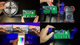
Matt from MKSmartHouse presents a complete hardware assembly guide for an ESP8266-based LED strip controller. The video covers the full parts list, tools, and step-by-step soldering of a custom PCB, followed by enclosure modification and LED strip connection. Software integration with MQTT and OpenHAB is promised for a follow-up video.
Matt from MKSmartHouse introduces the LED Strip Control project and covers all required parts and assembly steps.
Includes 1-pin/2-pin/3-pin/4-pin headers, DC jack, TIP122 transistors, 470-ohm resistors, ESP8266, buck converter, custom PCB, 5050 LED strip, enclosure, and 12V 3A power adapter.
Soldering iron with ST7 tip, flux, steel wire, solder, wall tac, PCB holder, helping hands, wire strippers, cutters, screwdrivers, dremel, multimeter, drill bits, and drill.
Links to all parts and tools are on the MKSmartHouse website; kits and pre-assembled devices are also available.
The custom PCB provides stable, strong connections and eliminates guesswork, making multiple builds easy; gerber file is shared on the website.
Place the PCB in a holder; labels mark component slots. Solder less sensitive components first.
Solder the four 1-pin male headers into J1, J2, J4, J5, then the 2-pin and 3-pin male headers into J8 and J6.
Solder the 4-pin female header with short pins into J7 and the DC jack into the Power Plug1 slot.
Solder three 470-ohm resistors into R2-R4 and three TIP122 transistors into Q2-Q4, with markings facing B C E labels.
Solder the 90-degree header into J3, then ESP8266 into U1 with flux on all pads; mount buck converter on 1-pin headers and solder corners.
Plug in 12V adapter, use multimeter to check output, and adjust gold screw on buck converter to 3.3V.
Unplug power, then place 2-pin jumpers over the power header and the PGM side of the 3-pin header.
Fold down transistors, mark and cut a rectangular hole for the header with a dremel, and file edges clean.
Use a 6.5mm drill bit to drill down the four standoffs inside the enclosure so the PCB fits in height.
Insert the 4-pin female header with long pins into the LED strip and connect it to the PCB, aligning the white wire with the W mark.
Hardware is complete; software and MQTT/OpenHAB integration will be covered in the next video.
What voltage should the buck converter be adjusted to?
3.3 volts.
04:41
Which type of transistor is used in the LED strip controller?
TIP122 transistors.
03:18
What is the resistance value of the resistors placed in slots R2, R3, and R4?
470 ohms.
03:03
How should the TIP122 transistors be oriented when soldering?
The side with writing should face the B C E markings on the PCB.
03:18
What tool is used to cut the rectangular hole in the enclosure?
A dremel.
05:18
What size drill bit is used to drill down the standoffs?
6.5 mm.
05:34
Which wire of the LED strip aligns with the W mark on the PCB?
The white wire.
06:04
Why did the creator design a custom PCB?
For stability, strong connections, no guesswork in assembly, and to easily make many units for the house.
01:47
What tip is recommended for the soldering iron?
ST7 tip.
01:05
Where can the gerber file for the PCB be obtained?
On the MKSmartHouse website.
01:47
Custom PCB rationale
Explains the decision to design a custom board for reliability and batch production instead of using loose wiring or a breadboard.
01:47Transistor orientation
Clear instruction on aligning TIP122 markings with the PCB silkscreen, a common source of assembly errors.
03:18Precision voltage adjustment
Demonstrates a safe way to set the buck converter to 3.3V before connecting the ESP8266, preventing damage.
04:27Enclosure fitting workaround
Folding transistors and cutting/drilling the case are practical tips for getting a custom PCB into a standard enclosure.
05:05Wire-color alignment
Quickly identifies the white wire as the reference for correct LED strip polarity, avoiding a common wiring mistake.
06:04[00:00] Hey guys Matt here from MKSmartHouse.com and in this video I am going to show you how to build the LED Strip Control. So, in this video we are going to go over all the parts required for the LED Strip Control
[00:18] and then we are going to make it. To start off with the parts we are going to need 4 1 pin male headers, 1 4 pin female header with long pins, 1 4 pin female header with short pins, 1 4 pin 90 degree male header, 1 3 pin male header, 1 2 pin male header,
[00:37] 2 2 pin jumpers, 1 DC Jack, 3 TIP 122 Transistors, 3 470 ohm resistors, 1 esp8266, 1 buck converter,
[00:51] 1 custom PCB More on that later, 5 meters of 5050 led strip, black enclosure, wall tac and a 12 volt 3 amp power adapter. For tools we are going to need a soldering iron with
[01:05] ST7 tip, flux, steel wire, solder, wall tac, PCB holder, helping hands, wire strippers, small wire cutters, small flat screwdriver, phillips screwdriver, dremel, multimeter, drill bits, and a drill. That is everything that we will need. The links to all the parts
[01:21] and tools will be over on my website, link is in the description. On my website you will also find the kit for this device, so instead of buying all the parts separately you can buy 1 kit and get all the parts fast and at the same time. There is even an option to
[01:34] get the device assembled so all you have to do is install its software and set it up. In the beginning I did say custom circuit board because to make this easier I designed a custom circuit board so that way not only will it be very stable and have strong connections
[01:47] with no guess work in assembling it but, also so I can make many of them really easily for my house. I have provided the gerber file on my website as well as where to get it made. You can also buy the PCB on my website, which is the easiest and fastest way to get them.
[02:02] Since all the connections are already made on the circuit board all we have to do is solder the components on to the board. First let's take the circuit board and put it into the circuit board holder. If you look closely at the circuit board you will see that there
[02:14] are labels next to the component slots, when I say where to put the component that is what I will be referring to. I like to solder from the less sensitive components to to most sensitive so, let's start off with the 4 1 pin male headers, put them into slots J1, J2, J4 and
[02:31] J5. Then solder them in. If you want to know how to solder or how I solder then check out my guide for the door sensor because in that video I went over it in detail. Next take the 2 pin male header and solder it into J8. After that take the 3 pin male header and
[02:48] solder it into slot J6. Following that take the 4 pin female header with short pins and solder it into slot J7. For the Power Plug1 slot we are going to solder in the DC jack.
[03:03] Now Grab the 3 470 ohm resistors and solder them into slots R2 R3 and R4. To put them in the slots I bent their leads. Once they were soldered in I also cut excess of the
[03:18] leads on the other side of the PCB. Next take the 3 TIP 122 transistors and solder them into slots Q2 Q3 and Q4. When you put them in the slots, the side of the transistor with
[03:30] writing should be facing the markings B C E on the PCB. Now take the 4 pin 90 degree male header and solder it into slot J3. Once that is soldered in flip the pcb over and
[03:46] solder the Esp8266 into slot U1. I recommend putting flux on every single pad of the esp8266 and of the circuit board and then solder it in. The last component we have to solder in
[04:00] is the buck converter. Grab the buck converter and place it on the 4 1 pin male headers. Make sure the out side of the buck converter is next to the MK-SmartHouse logo. Once it
[04:13] is nicely seated solder the 4 corners of the buck converter to the pins. Great everything Next grab the power adapter and plug it into power as well as into the PCB. Then take the
[04:27] multimeter and put the black probe into the hole of the buck converter and then take the red probe and hold it over the out + terminal of the buck converter. Using a small flat
[04:41] screw driver on the gold screw, adjust the voltage of the buck converter to 3.3 volts. Once it is adjusted unplug the power adapter from the PCB and then take the 2 pin jumpers
[04:53] and put one over the power header and the other over the PGM side of the 3 pin header. Everything to do with the PCB is now complete, so let's move on to modifying the case to
[05:05] make the PCB fit. Before we modify it fold down the TIP122 transistors on the PCB, this is so they can fit. Then take the side of the pcb with the 90 degree header and put
[05:18] it into the case. Using a sharpie mark the top of the header on the case. Then use a dremel to cut a rectangular hole. After the hole is cut use a small file to clean up the edges. Take the PCB and make sure the hole lines up. You may have noticed that the PCb
[05:34] still does not fit in the enclosure in terms of height. So grab a 6.5 mm drill bit and put it into a drill. I used a drill press but you can use a normal hand drill and drill down the four standoffs inside the enclosure. If you put the PCB in the case and close the
[05:50] Now let’s move onto the LED strip, the only thing we have to do is take the 4 pin female header with long pins and stick it into the female end of the LED strip. Next remove the
[06:04] lid of the case and connect the LED Strip, the white wire of the LED strip should lign up with the W mark on the PCB. That is it for the hardware of the actual device now all it needs is some software which will be in the next video. If you need any
[06:18] of the parts shown in the video you can buy a kit, or the PCB to make the device at the link in the video description. Alright thank you for watching and If you have any questions leave them in the comments section below or head over to mksmarthouse.com/forum. Good
[06:31] Bye!
⚡ Saved you 0h 06m reading this? Transcribe any YouTube video for free — no signup needed.