
Every Part Needed for Smart Blinds
45sQuick-fire parts list gives DIYers the complete shopping list in one clip.
▶ Play Clip"A genuinely complete hardware guide with no fluff, exactly matching the title's promise."
In this hardware build guide, Matt from MKSmartHouse.com walks through every component and step needed to assemble a custom ESP8266-based blinds controller that works with MQTT and OpenHAB. The video covers the full parts list, a custom PCB, soldering process, USB power cable wiring, servo motor cable assembly, and mechanical mounting, ending with a fully built hardware device ready for software.
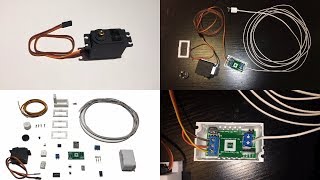
The build requires a 2-pin PCB terminal, 4-pin female header, 3-pin male header, 3-pin terminal, 2-pin jumper, ESP8266, 5V-to-3.3V regulator, custom Blinds Control PCB, plastic enclosure, 10ft of 22-gauge 2-conductor cable, USB connector, servo adapter plate, servo motor, multiple screws, 6ft servo motor cable, servo connectors, blinds adapter, and servo mount.
Any USB 5V wall adapter (like a phone charger) works, but it must be powerful enough because the servo motor draws significantly more power than other devices in this project.
The servo-to-blinds adapter and servo mount are not standard parts. They can be 3D-printed using the STL files provided on the creator's website.
Tools include a soldering iron with ST7 tip, flux, steel wire, solder, wall tac, PCB holder, helping hands, wire strippers, small wire cutters, and a small flat screwdriver.
The custom PCB is designed for stability, strong connections, and no guesswork during assembly. It also makes mass production easy. Gerber files are available on the website.
Solder from the least sensitive components to the most sensitive. Start with the 2-pin terminal in J1, then the 4-pin female header in J2, and the 3-pin male header in J3.
Place the 2-pin jumper on the 3-pin male header above the PGM side before flipping the PCB. Then solder the ESP8266 last on the back, applying flux to every pad for clean joints.
Strip the 22-gauge 2-conductor cable, slide the wire boot and plastic boot onto it, then solder the black wire to the far-left pin and the red wire to the far-right pin of the USB connector. Add hot glue and secure the boots.
Cut the servo motor cable to 6 feet, strip the individual wires, insert the orange wire into a male metal connector, and assemble the connector. Connect the other end to the PCB: brown to -, red to +, and orange to D.
Mount the servo motor to the servo mount with two screws, file down edges if needed for spacers, attach the adapter plate, and secure the servo-to-blinds adapter. You may need to file the square of the adapter for the blinds shaft to fit.
Place the blinds control into the plastic enclosure, connect the male and female servo connectors using the servo coupler, and use a Dremel to cut off the tabs on the other side of the servo motor so it fits into the blinds.
After about seven and a half minutes of assembly, the hardware is complete and ready for firmware. The build uses readily available parts plus a custom PCB, and next steps are covered in a software/installation video.
MKSmartHouse website
link
MKSmartHouse forum
link
STL files for 3D-printed parts
link
Gerber files for custom PCB
link
Parts kit for blinds control
service
Pre-assembled blinds control device
service
Soldering iron with ST7 tip
tool
Dremel
tool
Matt (MKSmartHouse host)
person
Door sensor soldering guide video
link
What is the first component soldered to the PCB?
The 2-pin terminal in J1.
02:58
In what order does the creator recommend soldering components?
From the least sensitive components to the most sensitive components.
02:58
Which wires go to the far-left and far-right pins of the USB connector?
Black wire to the far-left pin, red wire to the far-right pin.
04:21
Where do the brown, red, and orange wires of the servo motor cable connect on the PCB?
Brown to -, red to +, and orange to D.
05:38
Why should the 5V USB wall adapter be powerful?
Because the servo motor takes more power than the other devices in the project.
01:11
Where can you get the STL files for the 3D-printed servo mount and adapter?
On the creator's website, mksmarthouse.com.
01:25
What is the purpose of the custom PCB?
It makes assembly stable and reliable, with strong connections and no guesswork, and it is easy to mass-produce.
02:20
Where should the 2-pin jumper be placed on the 3-pin male header?
On the PGM side.
03:50
What tool is used to cut off the tabs of the servo motor?
A Dremel.
06:53
How long should the servo motor cable be cut?
6 feet.
05:03
Custom PCB design for reliability
Shows how designing a custom board eliminates assembly guesswork and makes the build repeatable at scale.
02:20Soldering sensitive components last
A practical technique that reduces the risk of heat damage to delicate parts like the ESP8266.
02:58Filing the adapter for a perfect fit
A simple mechanical adjustment that ensures the 3D-printed adapter mates correctly with the blinds shaft.
06:21Modifying the servo with a Dremel
Demonstrates a creative hardware workaround when off-the-shelf components don't fit the intended installation.
06:53Power supply sizing matters
Highlights a common failure point in servo-based projects: underpowered wall adapters.
01:11[00:00] Hey guys Matt here from MKSmartHouse.com and in this video I am going to show you how to [Intro] So, in this video we are going to go over all the parts required for the Blinds Control
[00:18] To start off with the parts we are going to need 1 2 pin PCB Terminal, 1 4 pin female header, 1 3 pin male header, 1 3 pin terminal, 1 2 pin jumper, 1 esp8266, 1 5v to 3.3v regulator,
[00:37] 1 custom Blinds Control PCB, more on that later, 1 plastic enclosure, 10ft of 2 conductor 22 guage cable, 1 Male usb connector, 1 servo adapter plate, 1 servo motor, 4 servo to blinds
[00:55] adapter screws, 1 adapter plate screw, 2 servo mount screws, 6ft of servo motor cable, 1 set of servo motor connectors, 1 servo motor blinds adapter, 1 servo motor mount and a
[01:11] The wall adapter can be any usb 5v adapter like a phone charger just make sure it is powerfull because the servo motor takes more power than the other things we have made.
[01:25] You may have noticed that the servo to blinds adapter and the servo mount are not normal To get these parts you can either 3D print them yourself with the STL files on my website
[01:39] For tools we are going to need a soldering iron with ST7 tip, flux, steel wire, solder, wall tac, PCB holder, helping hands, wire strippers, small wire cutters, small flat
[01:52] That is everything that we will need. The links to all the parts and tools will be over on my website, link is in the description. On my website you will also find the kit for this device, so instead of buying all the
[02:05] parts separately you can buy 1 kit and get all the parts fast and at the same time. There is even an option to get the device assembled so all you have to do is install In the beginning I did say custom circuit board because to make this easier I designed
[02:20] a custom circuit board so that way not only will it be very stable and have strong connections with no guess work in assembling it but, also so I can make many of them really easily for I have provided the gerber file on my website as well as where to get it made.
[02:34] You can also buy the PCB on my website, which is the easiest and fastest way to get them. solder the components on to the board.
[02:46] First let's take the circuit board and put it into the circuit board holder. If you look closely at the circuit board you will see that there are labels next to the to.
[02:58] I like to solder from the less sensitive components to to most sensitive so, let's start off with the 2 pin terminal, take the terminal and put it in J1. If you want to know how to solder or how I solder then check out my guide for the door
[03:13] sensor because in that video I went over it in detail. Next take the 4 pin female header and put it into J2 and solder it in.
[03:25] If the leads get long and stick out cut them with wire cutters. Then take a strip of the male header and using the wire cutters make a header that is 3 pins Take that 3 pin male header and solder it into J3.
[03:38] For slot U2 take the 5v to 3.3v regulator and match up its leads to the board and solder Before we flip over the PCB we are going to put the 2 pin jumper on the 3 pin male header
[03:50] and above the PGM side. Great now we have one component left to solder and that is the esp8266, it is on the back I recommend putting flux on every single pad of the esp8266 and of the circuit board and
[04:08] I am talking about the 5 volt power cable. Then take one end of the wire and strip it to expose the 2 conductors. Strip a little of the each conductor and then take wire boot and plastic boot of the usb
[04:21] connector and slide it over the 2 conductors. Next take the helping hands and put the 22 gauge wire in one of them and the usb connector Then solder the black wire to the far left pin and the red wire to the far right pin.
[04:36] Now put some hot glue on the connector and slide over the plastic boot and the wire boot. If you want you can connect the USB to the 5v wall adapter but do not plug it into the Almost done, strip the other end of the 22 gauge cable and then loosen the two screws
[04:51] Then take the red wire and put it into the hole parallel to where it says + and the black into the hole above the - symbol and tighten the screws.
[05:03] Next grab the servo motor cable and cut it to a length of 6 feet. Take the cable and separate the individual wires and strip them to expose the conductors. Separate one of the male metal pieces and put the orange wire into it.
[05:22] Once the wires are complete stick them into the black plastic piece of the connector. Take the other end of the servo motor cable, separate the wires, strip them and fold their
[05:38] Then loosen the 3 pin terminal screws on the pcb. Put the brown wire into the - slot, red into the + slot and then Orange wire into the D Once those are in tighten their screws down.
[05:53] Next grab the main part of the servo mount and place the servo motor onto it. Secure the servo motor by taking the 2 servo mount screws and screwing them in with a philips You may need to file down some of the edges of the servo mount in order for the spacers
[06:09] After that grab the servo adapter plate and put the black adapter plate screw into it. Now take the servo to blinds adapter and put the side with no screw holes down onto the
[06:21] You may need to file down the square of the adapter in order for the blinds shaft to fit. Then put the adapter plate on top of that and screw it down using the 4 servo to blinds Grab the plastic enclosure and put the blinds control into the enclosure.
[06:38] Now take the the servo coupler that comes with the servo connector and put both the male servo connector and the female servo connector into the coupler. Finally, since the servo motor is really wide, it will not fit into the blinds so, grab a
[06:53] dremel and cut off the tabs of the other side of the servo motor. Once everything is done we should have the following things, power cable connected to the blinds control, the blinds control box with lid, servo motor cable connected to the
[07:06] servo motor and on the servo mount, servo mount spacers and the servo to blinds adapter We will attach that in the final installation video.
[07:18] That is it for the hardware of the actual device now all it needs is some software which If you need any of the parts shown in the video you can buy a kit, the PCB or 3D printed parts to make the device at the link in the video description.
[07:33] section below or head over to mksmarthouse.com/forum. Good Bye!

⚡ Saved you 0h 07m reading this? Transcribe any YouTube video for free — no signup needed.