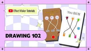

Turn Clocks Into a Matching Game
42sShowcases a unique interactive concept that viewers will want to try immediately.
▶ Play Clip"Delivers exactly what the title promises — a thorough drawing tutorial with zero clickbait."
This tutorial from Effect House Maker's Drawing 102 series demonstrates how to build a gamified matching game called 'clock connect' from scratch. The creator, Varun Raikar, walks through asset setup, scene assembly, visual scripting, and publishing, showing how to connect digital and analog clocks by drawing lines. The video emphasizes the flexibility of the approach, which can be adapted to any theme.
The effect shows two groups of clocks (digital and analog) that players connect by drawing a line between matching pairs. The logic can be applied to any theme.
Start by creating a new project in Effect House Maker and upload all required assets: background, three digital clock images, three analog clock images, two outline images, and a restart button.
Add the background image and scale it to full screen. Then add digital clock images at the bottom and analog clock images shuffled along the top, with outline overlays for each.
The draw object automatically adds a visual script that handles drawing functionality. The script graph appears at the bottom.
Create a win message text ('You did it!') and an instruction text ('Match the time on the digital clock to the correct analog clock'). Also add a restart button initially placed off-screen at X=1000.
Variables include active digital clock (number, -1), active analog clock (number, -1), pair one/ two/three done (booleans, false), and game complete (boolean, false).
Use start, set property, and drag nodes to show the instruction when the effect opens and hide it as soon as the user starts drawing.
Set up six 'object contains position' nodes to check if the drag start position is inside each clock. On true, store the active clock number and show its outline.
Use get variable, equal, and AND nodes to check if active digital clock and active analog clock match a pair and that pair isn't already done.
Reset active digital and analog clock variables to -1 on the on-start output of a new drag node, so leftover values don't trigger incorrect matches.
If a stroke doesn't connect a valid pair, hide all outlines, reset pair-done booleans to false, and clear the canvas using the draw node's clear canvas input.
Check if all three pair-done booleans are true using frame update and if node. Gate it with a limiter (trigger limit 1) to set game complete only once.
Use transition nodes to fade in the win message (opacity from 0 to 1 over 1s) and slide the restart button into view (X from 1000 to 250 over 1.5s).
Route the drag output through a not/if gate so drawing is disabled once game complete is true.
Create time (number, default 0) and timer running (boolean, default false) variables. Use frame update, effect time, and number to text nodes to display elapsed time, and stop the timer on win.
Preview on phone via QR code, upload a thumbnail, set effect name ('clock connect'), write a description, set instruction to 'draw on the screen', and submit.
The tutorial successfully takes a beginner from blank project to a fully functional, polished matching game using the Drawing component's visual scripting. It demonstrates reusable logic patterns like variable resets, once-only triggers, and input gating that can be adapted to many other AR effects.
What is the default value of the active digital clock variable?
-1 (minus one), meaning nothing is selected.
04:38
How many variables are needed for the base clock connect effect?
Six: active digital clock, active analog clock, pair one done, pair two done, pair three done, and game complete.
05:07
Which node checks whether a given position is inside an object?
Object Contains Position node.
07:09
Why do we reset active digital/analog clock variables on every new stroke?
To prevent leftover values from causing false matches when a stroke starts from empty space.
12:08
What node ensures the win condition fires only once?
Limiter node with trigger limit set to 1.
15:58
What values are used in the transition to fade in the win message?
Start value 0, end value 1, duration 1 second.
16:12
How is drawing blocked after the game is complete?
The game complete variable is passed through a not node into an if node that routes the drag output.
18:29
What are the two variables needed for the optional timer?
time (number, default 0) and timer running (boolean, default false).
19:28
What is the final sequence to publish the effect?
Preview on phone, scan QR, upload thumbnail, fill effect name and description, set instruction, then submit.
21:32
Which keyboard shortcut duplicates nodes in the visual script on Windows?
Control D (Command D on Mac).
05:53
Flexible game logic
The same matching-game structure can be applied to any theme, making this a reusable template for many effects.
00:28Instruction visibility best practice
Shows a clean pattern for showing instructions on launch and hiding them on first interaction.
06:23Resetting variables on stroke start
A simple but critical fix that prevents false matches and keeps the game logic predictable.
12:23Using a limiter for one-time win logic
The limiter node guarantees the win sequence only triggers once even though frame update runs every frame.
15:58Adding a timer for deeper gamification
Shows how a few extra nodes can add a competitive layer to the effect, significantly increasing engagement.
19:28[00:02] 102. In drawing 101, we covered the drawing template from the ground up. In this tutorial, I'll show you how to build a gamified effect using the drawing component. The effect we're building is called clock connect. In
[00:14] this effect, the player sees two groups of clocks on the screen. One is digital and another one is analog. They have to connect each digital clock to its matching analog clock by drawing a line between them. What makes this
[00:28] interesting is how flexible it is. You can apply this same logic to almost any theme to create a new effect. Here are a few examples. To get started, open Effect House Maker on your browser. Since we're building this effect from
[00:43] scratch, I'll click on new project. First, we will upload our assets. To do that, I'll switch to the assets tab and click on upload. For this effect, you will need a background image,
[00:56] three digital clock images, three matching analog clock images, two outline images for the clocks, one for digital and one for analog, and finally a restart button image. I'll select all of them and click open.
[01:11] Once uploaded, I'll switch to the objects tab and start assembling the scene. First, I'll add the background image. I'll right click, go to add object, image and video, images, image. Here, click on the drop down and select
[01:26] the background image. I will scale up the preview panel to see Let's adjust the background to cover the whole screen. For that, I will go to the whole screen. For that, I will go to the properties panel and change the width to
[01:40] You'll notice it will automatically adjust the height to 1280 pixels because I have the lock aspect ratio box checked. Next, the drawing object. Right click in the objects panel, image and video, here select the draw object.
[01:57] Effect House Maker automatically adds the visual script that makes drawing work. You can see it here at the bottom. I can now draw on the screen. For now, I'll reset the effect and hide the visual script area.
[02:11] Next, for the clock, I'll add an image object. Here, I will select my first digital clock and I'll rename it to digital clock one. Scale its width to 150 pixels and place it in the bottom half of the screen. You
[02:27] can also use the XY arrows in the scene view to position it, but I like using placement. Then, I'll duplicate it for the other two clocks.
[02:39] I'll swap their image assets and change their X positions. Now, I'll do the same for the analog clocks and place them across the top half of the screen. Make sure their positions are shuffled so they don't line up directly above their
[02:52] they don't line up directly above their matching digital clock. add an outline object that frames it. To do this, I'll simply duplicate the clock
[03:07] object, assign the outline image. I'll rename it to digital clock one outline. script. I'll repeat the same for the script. I'll repeat the same for the rest of the clocks.
[03:30] them because we will control their visibility using the visual script. Next, we will add two text objects, one for instruction and one for win message. Just right click and add a text object. Here, I'll rename it to win message. And
[03:45] in the text contents, I'll write you did it with an exclamation mark. I'll adjust its position. For the instruction, I'll keep it simple and I'll write match the time on the digital clock to
[03:59] the correct analog clock. Once done, I'll hide them for now. Next, I'll add an image object for the restart button and I'll assign the asset, resize it, and move it out of the view by setting
[04:11] its X position to 1,000. Finally, to show the user, I'll add a body segmentation, resize it, and reposition it on the I'll position it on the bottom right side.
[04:24] Great, our scene is assembled. Now, let's set up the variables. To do that, toggle the visual script view and open the variables panel. Click on this plus icon to create a new variable. The first variable we'll create is active digital
[04:38] clock. It is a number type and default value will be minus one. This stores which digital clock the player started drawing from. Second is active analog clock.
[04:52] It is also number type with default value minus one. This stores which analog clock the stroke is currently on. We start both at minus one because minus one means nothing is selected. Next, we need three booleans, one per pair. We'll
[05:07] call it pair one done. The default value is false. Pair two done and pair three done. And last, game complete. This is a boolean type with a default value false. These are all the six variables we need to build this effect.
[05:22] Now, we build the logic step by step. I will close the objects panel, increase the size of the visual script area, and resize the preview panel. Before we start building the logic, here are a couple of keyboard shortcuts I use
[05:38] to work faster and more efficiently inside the visual script. Number one, hold down the middle mouse button to drag and move in the scripting area. Alternatively, you can hold on the space bar plus click and drag with any mouse
[05:53] button to move around the scripting area. To duplicate a node or a group of nodes, first select them and use the shortcut command D on Mac or control D if you're on Windows. Use command or control Z to undo, command shift Z or
[06:08] control Z to undo, command shift Z or control shift Z to redo, and finally, backspace or delete key to delete a connection, node, or a group of nodes. Now, let's start with the logic. This script graph was automatically created
[06:23] when we added the drawing component. We'll leave it as it is for now and move to an empty area. Step one, show instruction. For a game effect, it's best practice to show the instruction when the user opens the effect. To do
[06:37] this, I'll right click, search for a start node, and a set property node. Set the object to instruction, property to visible, and connect the start node's execution output port into the set visible's start input port.
[06:53] Then, I'll search for a drag node and duplicate the set visible node. I'll use the on start output port from drag to set the visibility of the instruction text to false, so the instruction is hidden the moment user starts drawing.
[07:09] Next, we need to know which clock the player starts drawing from and show its outline. For this, we'll use object contains position node. It checks whether a given position is inside a specific object and outputs a boolean.
[07:24] We'll set up six of them, one per clock. Search for an object contains position and set the object to digital clock one. I'll use the same drag node we added earlier. Take the current position output from drag and connect it to the
[07:38] position input on the object contains position. I'll add an if node, connect the output from object contains position into the condition of the if. Connect the dragging execution port from drag into the start input port of the if.
[07:54] When this is true, the player is inside digital clock one zone. I'll add a set variable node, from the drop down select active digital clock, take the true output from if node and use it to set the active digital clock variable to
[08:09] one. Next, I'll add a set property node, select the object to be digital clock select the object to be digital clock one outline, and property to be visible. variable and connect it to the start input port
[08:25] on the set visible node. With this logic in place, whenever I'm dragging from digital clock one, it will store the active digital clock number and show its outline. As I build the effect, I'll keep testing it in the preview panel.
[08:39] For digital clock two, we just need to duplicate the same logic and change the parameters. I'll select these four nodes, duplicate them, and connect the false execution port from the previous if into the start input port of the next
[08:54] if. This creates a sequence logic. Now, I will connect the current position from drag into the position input on the second object contains position. Change the object to digital clock two, active
[09:09] digital clock variable to two, and set digital clock two outline to be visible. On testing, digital clock one and two are both getting highlighted as I draw from them. Let me quickly duplicate this logic for the rest of the clocks.
[09:40] should look like. Make sure the objects and variables are set properly in each of the nodes. I'll verify this in the preview panel by drawing a line from each of the blocks. As I draw, it should show the outline around them. This logic
[09:55] is now working. Next, we check if they connected a right pair. I'll add a get variable node, set it to active digital clock, duplicate this and set it to
[10:07] active analog clock. Add two equal nodes. Connect the get variable value to nodes. Connect the get variable value to input one on both of them. Set input two to be one. Finally, combine them using and node.
[10:21] Our first condition is ready. Next, I will duplicate the get variable node and will duplicate the get variable node and set it to pair one done. Connect it to a not gate. This is our second condition. Finally, we combine both the conditions
[10:35] Finally, we combine both the conditions using another and node. node and an if node. Connect the drag output to the start of
[10:48] the if node. The logic which we created goes into the condition on the if node. So, true here means a pair is matched. We'll use the true branch to set the pair one done variable to true. So, to recap, this logic is checking if active
[11:04] digital clock and active analog clock variables are equal to one and it is also checking if they are not already matched. When this condition is satisfied, then it is setting the pair one done boolean to true. For the
[11:19] remaining two pairs, I will just duplicate the same logic and change the parameters to match the remaining clock pairs.
[11:54] >> This is how it should look like once you add clock pair two and clock pair three. Make sure you connect the false output from the previous if node to the start input of the next if node to continue the sequence. But, there is a small
[12:08] problem with this. Active digital clock and active analog clock hold their last values even after the player stops dragging. So, if a new stroke starts from an empty space, a leftover value could trigger a false match. To fix
[12:23] this, we'll reset the active clock variables on every new stroke. Add a new drag node. Add a set variable node. Set it to active digital clock. Duplicate it
[12:35] and set the second one to active analog clock. clock. Use the drag node's on start output port to set the active digital clock variable to minus one.
[12:47] Take the next output from the first set variable node and use it to set the active analog clock variable to minus one. Now, every stroke resets the active clock variables. Next, we will clear the canvas and hide the outlines on a wrong
[13:02] attempt. A wrong attempt means they have connected non-related clocks. We will run this check after the user stops drawing. I'll add an if node and connect the on start output from drag into the start of the if. For the
[13:18] condition, we need two things to be true. I'll simply duplicate the get variable nodes that we have previously created and bring them over here. I will check if both of them are equal using an equal node.
[13:33] Our first condition is ready. For the second condition, we need to check if any of the pairs are already set to done. I'll quickly set this up by duplicating the get variable nodes and set it to pair one done, pair two done,
[13:47] and pair three done. I will combine their output using or node, whose result will become true if any of these pairs are true. Finally, I'll combine both conditions using and node and feed that to the condition of the if. To recap,
[14:04] the logic here is if this condition is true, then the user has connected a right pair. But, if this condition is false, that is when we clear the canvas.
[14:16] So, I will take the false output from the if and use that to hide all the outlines. I will add a set property node and set it to digital clock one outline property to visible and make sure it is set to false.
[14:32] I'll connect the false in output from the if into the start of the set visible node. I'll duplicate this same node for the rest of the outlines and connect them in a sequence. Next, I'll add a set variable node and
[14:46] set the pair one done variable to false. I'll duplicate it for pair two done and pair three done. Finally, I'll bring the drawing script graph here. Take the next output from the last set variable node and feed that into the
[15:02] clear canvas input port of the draw node. Great. Now, our logic clears the canvas on a wrong attempt. I'll quickly test it out in the preview panel. I'll also check by connecting a right pair. As you can see, the drawing is not
[15:17] getting cleared. Now, for the win logic, we need to check if all pair done booleans are true. I'll duplicate the get variable nodes we created earlier for pair done flags. Combine them using and nodes. Add a
[15:31] frame update node along with an if node. Feed the logic into the condition of the Connect the next output from the frame update into the start of the if. If this
[15:43] condition is true, it means all three pairs are matched correctly. Because the frame update node runs every single frame, we don't want the win condition firing over and over. To fix this, I'll gate it with a limiter node. I'll search
[15:58] for a limiter node and connect the true output from the if node into the start of the limiter. Make sure the trigger limit is set to one. I'll take the on trigger output from the limiter and use it to set the game
[16:12] complete variable to true. I'll add a transition node to fade in the win message. Start value to zero, end value to one, duration to 1 second.
[16:24] I'll connect the next output node from set variable into the start of the transition node. On start, I will set the visibility of the win message object to true using a set property node. On change, I'll set
[16:38] the opacity of the win message and connect the value output from the transition into the opacity of the win message. Next, I will use the on end output from the transition node to start another transition node that will bring
[16:52] in the restart button on the screen. I'll set the start value to 1,000 because the current X position of the restart button is 1,000. End value to 250, duration to 1.5 second, curve to ease out. Take the on
[17:07] change output and use that to set the X position of the restart button and connect the value from transition into the X position. I'll trigger another transition node from the on start output of this
[17:21] transition node. Set the start value to zero, end value to 10,000, duration 200 seconds, curve to linear. I will use this to set the rotation of
[17:34] the restart button, so it looks like it is animated. Finally, I will trigger the effect reset using the restart button, so the player can play again. I'll use an object tap node, set the
[17:47] I'll use an object tap node, set the object to restart, trigger to tap start, object to restart, trigger to tap start, and search for reset state node. Connect the next output from object tap into the start of the reset state. This
[18:00] single trigger sets everything back to how it started in the effect, including the variables and the objects. Let me quickly test what we have built so far. quickly test what we have built so far. I'll connect all the right pairs,
[18:14] and you can see the win message fades in. As soon as I click on the restart button, the whole effect goes back to its beginning state. Awesome. We are almost done. Right now, even after the player wins, they can still keep
[18:29] drawing. Let's fix that. I'll first go to the area where we have the drawing logic. I'll get the game complete variable,
[18:44] run it through a not node, and feed the result into an if node as the condition. I will route the drag output through this if node via the true branch, and connect it back to the draw input port. With this logic, drawing only works
[18:58] while game complete is not true. The moment they win, game complete becomes true, and further drawing is blocked. Let me quickly test it in the preview panel. I'll connect the right pairs, and if I try to draw now, I won't be able to
[19:13] draw because drawing is blocked. Which is exactly what we want. By now, you should have a visual script graph which looks something like this. You can push this effect further by adding a counter timer. This is a great addition if you
[19:28] want to lean further into the gamification. To add a timer, create two new variables. First, time. It is a number type with the default value zero. Second, timer running. This is a boolean type with the default value false.
[19:46] I'll also add a text object to show the time. I'll adjust its font size, position, and style. To start the timer in the visual script, add a drag node. From its on start output, set timer running boolean variable to true. Next,
[20:03] to show elapsed time, add a frame update node and connect it into an if node with the condition get timer running variable. So, whenever the timer running variable is set to true, the true branch will fire. On true, get time variable
[20:20] and search for effect time node. We need frame interval, which is a number type. I will use a add node to add both of them. I'll connect the result to value input on the set variable node, and I'll
[20:34] connect the true execution output from if into the start of the set variable node. To display this, get time variable and pass it through a number to text node. I'll change the decimal places to two, and I'll use this to set the timer
[20:49] text. We also need to stop the timer on win. We'll do that back in our win logic. I'll duplicate the set variable node and set it to timer running. I'll use the on trigger output from limiter and connect it to set variable, and I'll
[21:04] set its value to false. Okay, let's test this out. As soon as I start drawing, a timer starts and once I have matched all of the clocks, the timer stops. If I click on reset, the timer also resets. That's how easy it is
[21:20] to add a timer. Since we have already tested the effect in the preview panel, do that, click on the preview on phone button and scan the QR code. Once
[21:32] submit button. Here, upload your effect thumbnail and click continue. Here, write your effect name. I'll call this clock connect. Keep the description simple. Write what the game is about and
[21:47] what the user has to do. Set the instruction to draw on the screen, then click submit. Congratulations, you have successfully built a matching game from scratch using the drawing component. With the drawing capabilities that we
[21:59] covered today, go create your own custom effect or explore the templates library to find an effect that you can extend with your own twist. For more effect maker tutorials, check the links in the description below. Thank you so much for
[22:11] subscribe button and I'll see you in the next one.
⚡ Saved you 0h 22m reading this? Transcribe any YouTube video for free — no signup needed.