
Blink an LED with Arduino in 45 Seconds
45sQuick, beginner-friendly tutorial with immediate visual payoff, perfect for short attention spans.
▶ Play Clip"Title perfectly matches content: it's a straightforward tutorial on blinking an LED with Arduino."
This tutorial teaches how to write an Arduino program and build a circuit to blink an external LED. It covers breadboard basics, circuit assembly, and coding in the Arduino IDE. The video also includes challenges to add a second LED and modify the blink pattern.
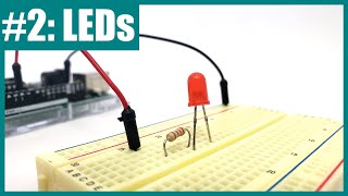
Learn to write an Arduino program and build a circuit to blink an external LED. Needed: Arduino, breadboard, two jumper wires, LED, resistor (150 or 220 ohm).
Breadboard has rows of five connected holes; adjacent rows are not connected. The center gap separates columns. Long side strips (buses) are connected vertically.
Insert LED legs into two rows (e.g., rows 10 and 12). Connect resistor in series by placing one end in the same row as the LED's positive leg. Use jumper wires to connect resistor free end to Arduino pin 12 and LED short leg to GND.
In Arduino IDE, create new sketch. In setup(): pinMode(12, OUTPUT);. In loop(): digitalWrite(12, HIGH); delay(1000); digitalWrite(12, LOW); delay(1000);. Upload to Arduino.
Add another LED to pin 8. Use ground bus for common ground. Copy pinMode and digitalWrite lines, change pin numbers. Both LEDs blink together.
To blink out of sync: set one LED high and the other low initially, then swap in the loop. Change two digitalWrite values.
By following this tutorial, you can successfully blink an LED with Arduino and expand the circuit to control multiple LEDs. Troubleshooting is normal; check connections and code for errors.
What resistor value is recommended for blinking an LED with Arduino?
150 or 220 ohms.
00:17
How are holes connected in a breadboard row?
Each set of five adjacent holes in a row are electrically connected.
00:44
What is the purpose of the resistor in the LED circuit?
To protect the LED by limiting current; too much current burns the LED, too little makes it dim.
04:05
Which leg of the LED is positive?
The longer leg.
02:51
What command sets an Arduino pin as an output?
pinMode(pin, OUTPUT);
07:04
What is the delay time in milliseconds for a one-second delay?
1000 milliseconds.
08:08
How do you connect multiple LEDs to ground without using multiple Arduino ground pins?
Use the breadboard's ground bus (the long strip marked with a minus sign) and connect it to one Arduino GND pin.
10:14
What does the digitalWrite(pin, HIGH) command do?
It turns the specified pin on (sets it to 5V).
07:42
How can you make two LEDs blink alternately (one on while the other off)?
Set one LED high and the other low initially, then swap in the loop.
14:42
Common Mistake: Series Connection
Shows a typical beginner error of placing components in adjacent rows thinking they are connected, then correcting it.
03:32Using Ground Bus for Multiple LEDs
Introduces a scalable method to connect multiple components to ground without using multiple Arduino pins.
10:14Alternating Blink Success
The satisfying moment when both LEDs blink out of sync like a railroad crossing light.
15:10[00:00] In this video, you will learn how to write a new Arduino program and build a circuit to blink an external LED. In addition to your Arduino, you will need a breadboard, two jumper wires, an LED, and a resistor.
[00:17] 150 or 220 ohm resistors work well. A breadboard consists of a grid of holes where you can insert wires in other parts like LEDs and resistors to build a circuit.
[00:30] You can easily remove and rearrange the parts if you make a mistake or want to build a different circuit. Each set of five holes that are adjacent to each other in a row are electrically connected to each other.
[00:44] So, for example, if I plug one jumper wire into the left end of this row in column A and plug another jumper wire into the right end of this row in column E, these two wires are now electrically connected.
[00:58] Adjacent rows are not connected to each other. So for example, if I move the red wire down to row 8, it is no longer connected to the black wire. Similarly, holes are not connected across the gap in the middle of the breadboard.
[01:14] So if I move the red wire over here to column F, even though it is in the same row, row 7, as the black wire, the two wires are not connected. If you flip your breadboard over you will see that normally they have an adhesive backing and you would leave this on.
[01:32] However, in this video I am going to remove the backing from this breadboard so I can show you how it works. So if we remove the backing, you can see these metal rows inside the breadboard and each of these is a set of metal clips.
[01:46] These are what grab onto the parts when you press them into the breadboard. but again you can see that each set of five clips is all connected to each other by a single piece of metal. So if I look at the back of the breadboard here, you can see what I described on the front.
[02:00] The pieces of metal are not connected between adjacent rows. There is insulating plastic in between them, and they're also not connected across this gap in the middle of the breadboard, but each set of five holes in half of a row is all connected to each other by a single one of these metal clips.
[02:17] The long vertical strips on the sides of the breadboard are called buses or rails, and they're connected a little differently, but we're not going to worry about them just yet. We are going to build a circuit that connects the resistor and the LED to the Arduino.
[02:34] Then we are going to write code that uses one of the Arduino's pins to turn the LED on and off. Note that when you're building your circuit, it's a good idea to unplug your Arduino. That way you're not working with a powered up circuit and this reduces the chance of short circuits if you make a mistake.
[02:51] Let's start with the LED. Look at it closely and notice that it has a long leg and a short leg. A long leg is the positive side that will be connecting to one of the Arduino's pins.
[03:03] Pick two rows in the breadboard to insert the LED legs. It doesn't matter exactly which rows but make sure you keep track of which end is the long leg or positive side. I'm going to put the LED legs in rows 10 and 12.
[03:17] Next, I'm going to connect the resistor so it is in series with the LED. This means electrical current can flow through the resistor and then through the LED. Now, your first instinct to do that might be to put the resistor so it is physically lined up
[03:32] or physically in series with the LED in the breadboard like this. However, remember how the holes are connected inside the breadboard. Adjacent rows are not electrically connected to each other. So there is no path for electrical current to flow from the resistor into the LED here
[03:49] because row 13 is not connected to row 12. In order for the parts to be electrically connected or in series I need to move the resistor over so one end of it is in row 12 next to the LED
[04:05] Once I've done that, I now have a path for electrical current to flow through the resistor, then through the LED. The purpose of the resistor here is to protect the LED by preventing too much current from flowing through it.
[04:19] If you forget the resistor completely or the resistance value is too small, then too much current will flow through the LED, causing it to burn out. However, if the resistance value is too large, then not enough current will flow through the LED and you won't be able to see it light up.
[04:36] That's why you can't just pick any resistor and it's important to choose the correct value. Again, 150 or 220 ohms both work well for this project. Next, I'm going to use my jumper wires to connect my circuit to my Arduino.
[04:52] I'm going to use my red wire to connect the positive end of my circuit, which is the free end of the resistor, to Arduino pin 12. In order for electrical current to flow, I need a complete path or a closed circuit.
[05:08] So I'm going to use my second wire to connect the negative end of my circuit, or the short leg of the LED, to the Arduino's ground pin, which is labeled GND. This gives me a closed circuit, or a complete path, for electrical current to flow out of pin 12, through the red wire, through the resistor, through the LED, and then through the black wire back to the Arduino.
[05:33] Now that we've built the circuit, we're ready to write the code to break the LED. This is a breadboard diagram made with a computer program. It makes it a little easier to see exactly which hole each part goes in on the breadboard.
[05:49] You can use it as a reference when you build your circuit. If you need to finish building your circuit, pause the video here before you continue. Double check to make sure all of your wiring is correct before you continue.
[06:08] Then open the Arduino IDE and get ready to write your first new program. To create a new program in the Arduino IDE, select File New.
[06:22] This will open a new window with a skeleton that includes the setup and loop functions, but they're both blank so you can add your own code. You can select File Save to save your program
[06:34] on your computer. Make sure you give it a name that makes sense to you and save it in a place where you'll easily be able to find it again. This time instead of loading an example program, you'll write your own code. Follow along as I type and pause the video if you need time to catch up
[06:51] on the typing. Remember that we connected our LED to Arduino pin 12. The first thing we need to do in our setup function is tell the Arduino that we're going to use that pin as an output. We're
[07:04] going to do that with the pin mode command. So type pin mode, make sure you capitalize the M, open parentheses, 12, and that tells the Arduino which pin we're going to use,
[07:16] comma, output in all caps. That tells the Arduino we're going to use the pin as an output. Then, make sure you end the line in a semicolon. All Arduino command lines must end in a semicolon,
[07:30] or you'll get an error when you try to upload the code. Now, that only needs to happen once, and then we want to blink the LED on and off forever, so we're going to go down to our loop function.
[07:42] To turn the LED on, we use the digital write command. Type digital write make sure you capitalize the W open parentheses 12 comma high That tells the Arduino to turn that pin high or on Then again remember to end the line in a semicolon Next we want that pin to stay high for one second so we going to use the delay command
[08:08] Type delay, open parentheses, but remember, don't just type one because the delay command works with milliseconds, not seconds. so we need to tell it to wait for 1,000 milliseconds.
[08:21] And again, end the line in a semicolon. After that, we want the pin to go low, so we're going to type, if we're right, open parentheses, 12, low.
[08:34] Note that the Arduino RDE automatically fills in the close parentheses for me when I type the open parentheses. And again, we're going to end that line in a semicolon. Finally, we're going to do another delay 1000.
[08:48] Notice that I forgot to hit the space bar twice there. You don't strictly need to, but to keep your code neat, code inside functions is usually indented by two spaces. That lets me look at this and easily tell that all of this code here is part of my loop function.
[09:04] Now, make sure you reconnect your Arduino if you had disconnected it when you were building your circuit. See that I have a notification here that my Arduino is not connected, so I've just plugged it back in, but then I need to reselect it from this drop-down menu.
[09:17] After that, you can upload the code. Once you've connected your Arduino and uploaded the code, if you built your circuit correctly, the LED should blink on and off.
[09:29] Now, here's a programming and circuit-building challenge for you. Add another LED that is connected to Arduino Ping 8. Edit your code so that LED blinks on and off at the same time as your first LED.
[09:42] Pause the video here and try it out. You might have built your circuit like this. I added a resistor and LED to the breadboard and then connected them with jumper wires to
[09:57] Arduino pin 8 and to one of the other ground pins available on the other side of the Arduino. That's okay because it will work, however the Arduino only has three ground pins available. So if you wanted to build a circuit with four or more LEDs, you would run out of ground pins.
[10:14] A better approach is to use the breadboard's buses, the long strips that are connected up and down the entire length of the breadboard. Normally you would use the black bus marked with a minus sign for the ground connection.
[10:27] So what I can do is take one of my ground wires that's connected to the ground pin on the Arduino and plug it in to that bus instead. That is going to make my ground connection available up and down the entire length of the breadboard.
[10:42] So unlike the rows in the middle of the breadboard, these buses are connected across the gaps. So this hole is connected to that hole and so on down the entire length of the breadboard, but they are not connected all the way across the breadboard.
[10:55] So this bus over here is not connected to this bus over there. So if I wanted my ground connection available on both sides of the breadboard, if I was building a bigger circuit, I would use another jumper wire to connect the left side to the right side.
[11:10] But since this circuit isn't that big, I'm not going to bother with that for now. What I will do is take my two jumper wires and use them to connect the LEDs directly to the ground bus. So now, I will still have both of my LEDs connected to ground, but instead of connecting them directly to the Arduino ground pins,
[11:29] I have connected them to this ground bus, which is then connected to a single Arduino ground pin with this jumper wire. One other thing to note here is that these long wires tend to get kind of messy as you build more complex circuits.
[11:43] You can wind up with a tangled nest of wires that is hard to trace and debug. So while these wires are good for making the connections to the Arduino they not always the best choice for these breadboard to breadboard connections That is where shorter jumper wires like this come in handy You can either purchase these in a kit or buy a pool of wire and wire strippers and cut them yourself So for example I going to replace this long wire
[12:08] with a short wire that makes the same electrical connection. It's just going from the ground bus to the LED but it's using a physically much shorter wire. I'm going to do the same thing with the other one. Replace that with a short wire and you see that this will make my circuit much
[12:22] neater so it is easier to trace the wires and debug the circuit to find the space. Finally, you will notice that I have not connected the positive or power bus here. That is useful if you need to provide your circuit with a fixed voltage like 5 volts or 3.3 volts from the Arduino,
[12:40] but you don't need to do that in this project. Here is another breadboard diagram that shows one way you can add a second LED to the circuit while making use of the ground bus. If needed, pause the video here and follow the diagram to finish building your circuit.
[12:56] But remember, there's more than one correct way to build the circuit on the breadboard, so it's okay if your circuit doesn't match this diagram exactly, as long as it still works. If you want to modify the program to also blink an LED connected to pin 8,
[13:11] you can do that mostly by copying and pasting existing lines of code. For example, I can copy and paste my pinMode command in the setup function, but I'm going to change the 12 to an 8 to tell the Arduino to use pin 8 as an output.
[13:27] Next, I'm going to copy and paste my digitalWrite command in the loop function, and again, change the 12 to an 8 to tell the Arduino to turn pin 8 high. I don't need to copy and paste the delay command.
[13:41] This tells the entire program to wait for one second, so pins 12 and 8 will already be high. I only need one delay command there. Then I'm going to copy and paste my digital write command, again, change the 12 to an 8.
[13:57] So now, the program tells the Arduino to set both pins 12 and 8 as outputs, turn both pins 12 and 8 high, wait for a second, turn both pins 12 and 8 low, and wait for a second.
[14:12] I can upload this new program to my Arduino. Now, when I reconnect my Arduino and upload the new code, I see both LEDs blink on and off at the same time.
[14:25] Here's one more challenge if you're up for it. Change your code so the LEDs blink such that one is on while the other is off and vice versa. Pause the video here and give it a try.
[14:42] If I want to change the program so the LEDs blink out of sync, I don't need to change much. I still need to set both of them as outputs. However, I don't want to set them both high initially. I want to set one of them high and set the other one low.
[14:56] Then, when I set the first LED low, I want to set the other one high. So all I had to do was change two of the highs and lows in the program. Again, if I upload this, now the LEDs should blink out of sync.
[15:10] After uploading the new code, I can now see that the LEDs blink out of sync, sort of like the warning light at a railroad crossing. Now, if at any point when following along with this video,
[15:22] your circuit didn't work as expected, that's okay. Even experts make mistakes, and it's easy to make simple mistakes when you're first getting started with circuits. Next up, we'll talk about some troubleshooting steps you can take to identify and fix problems in your circuit and your code.
[15:40] For more Arduino tutorials and lots of cool projects you can do with an Arduino, check out the links in the video description. For thousands of other fun, hands-on science and engineering projects, visit us online at www.sciencebuddies.org.
⚡ Saved you 0h 15m reading this? Transcribe any YouTube video for free — no signup needed.