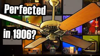
Why Your Electric Stove Pulsates
45sThe visual of a glowing stove element pulsing on and off is immediately intriguing and relatable, making viewers want to know the cause.
▶ Play Clip
"The title promises a deep dive into simmerstats, and the video delivers exactly that—a thorough, engaging explanation with no fluff."
This video explains the simmerstat, a century-old device that controls power output on electric stoves by cycling the heating element on and off. It covers the history, mechanics, and practical implications of this clever technology.
The simmerstat, also known as an infinite switch, controls power by pulsing the load on and off.
Variable resistors and transformers are impractical at high power levels due to size, cost, and heat generation.
Simmerstats have been used since the 1940s, with a patent from 1924.
Glass-top stoves use nichrome wire elements that heat up quickly, making the pulsing visible.
The glass is a ceramic that is transparent to infrared but opaque to visible light, causing the deep red glow.
A temperature probe opens a safety switch to prevent overheating.
Duty cycle control is the percentage of time a device is powered on, e.g., 50% duty cycle on a 1200W burner gives 600W effective output.
PWM is often used for signaling, while duty cycle control is for power modulation.
The simmerstat is a double-pole single-throw switch with a bimetallic strip that opens the circuit when heated.
The bimetallic strip bends when the copper bar heats up, opening the switch; it cools and closes again, creating the cycle.
The control knob turns a cam that adjusts the temperature at which the switch opens, thus changing the duty cycle.
The simmerstat is essentially a thermostat controlling the temperature of its internal heater, which acts as a proxy for duty cycle.
The memory effect causes longer pulses when increasing power, helping the burner reach the new target faster.
Simmerstats only work correctly with loads within a specific amperage range (8.9-11A), and their switching is slow.
Duty cycle control is cost-effective
Explains why simmerstats use duty cycle control instead of variable transformers, highlighting the engineering trade-offs.
03:20Simmerstats date back to 1924
Reveals the long history of this technology, showing it's not a modern invention.
04:00Bimetallic strip as a thermal switch
Demonstrates a simple mechanical principle that enables precise control without electronics.
15:02Simmerstat is a thermostat
Reframes the device's function, showing how temperature control can be used for power modulation.
22:19Memory effect improves response
Explains a subtle but important behavior that helps stoves react faster to knob changes.
26:54[00:00] It’s a glass-top radiant electric stove and if you’ve ever used one of these, The heating elements quickly begin to glow once switched on and you can feel the intense heat coming from them right away.
[00:16] but when you turn the control knob down to, say, medium power - It’s not still running but at half-power, it’s just off. But then, before too long, it comes back on…
[00:31] This pulsing behavior endlessly repeats. The answer is this funky component called an infinite switch, also known by the much, MUCH better name Simmerstat.
[00:46] It may not look like much, but each heating element in the cooktop is wired to one of these things, Let me show you - through the magic of buying two of them, and some other stuff,
[01:00] I’ve built this little box so I can control anything with a simmerstat. I’ll plug in a lamp to make what it’s doing obvious in addition to a mystery load on the other outlet Let me just stick on a control knob.
[01:15] Set to high, the simmerstat doesn’t interrupt power flowing through it at all, but when you move it off of the highest power setting, eventually power cuts out.
[01:29] Eventually, power returns. These periodic interruptions will repeat indefinitely, but as you turn the control knob further clockwise,
[01:41] Once you reach the medium setting, it will eventually settle into a point where it spends roughly equal time on and off. And then the trend will continue - if you go further, it only operates in brief pulses and those pulses get farther and farther apart.
[01:59] The reason the simmerstat behaves like this is because… Electrically, the heating elements in a conventional electric stove are merely resistors,
[02:11] But those resistors are huge! Each one in this stovetop is capable of outputting at least 1,200 watts and the larger ones pump out three kilowatts.
[02:23] That’s great for boiling water, but way too much power for more gentile cooking tasks like, oh, what’s a good example, To allow for that, we have to tame them and reduce their power output.
[02:37] You might think of adding a second resistor in series with the cooktop element, maybe even a variable resistor. but at these power levels, that theoretical resistor would have to be gigantic
[02:50] and as it restricted current flow it would generate quite a lot of heat of its own which is both wasteful energy-wise and would require cooling. So instead you might want to use a variable transformer such as a variac to produce a range of voltages to choose from -
[03:07] lower the voltage and you lower the power consumed by those heating elements. to handle this much power, that variable transformer would have to be quite large and thus quite expensive,
[03:20] So, to allow for fine control over the power output of the heating elements with minimal energy losses and component costs, This device produces any arbitrary power level by repeatedly switching its load on and off for varying periods of time,
[03:40] Before I explain what’s going on inside here, though, I want to point out that these things aren’t by any means a recent development. Coil-top stoves going back to the 1940’s use these same exact controls to modulate their power output.
[04:00] The first place I found it described is in this 1924 patent for Chester I Hall’s invention assigned to General Electric.
[04:12] Coil-style heating elements like this are also just giant resistors, so just as with the glass-top stoves which came later, the simmerstat was the most cost-effective way to regulate their output.
[04:25] That means coil-top stoves are exhibiting this pulsing behavior, too. However you generally aren’t aware of this happening with a coil-top stove because you can’t see it. The heat produced by these coils is generated by a thin wire element embedded in the center of the hollow metal tube which actually forms the coil.
[04:45] But the gap between the wire that produce heat and the walls of the tube is filled with a sand-like material. The sand fills the tube so it can be bent into different shapes with the wire inside staying centered,
[04:58] But to get the heat produced by the wire element out of the tube and into cookware, it must make its way to the outer surface, meaning it also has to warm up all the sand in the way which is a lot of thermal mass.
[05:14] The upshot is that it takes a long time for these elements to get hot enough to visibly glow, so the pulsing behavior of the simmerstat is visibly obscured. The elements below a glass-top stove are very, very different though.
[05:30] If I explained them would that be a tangent? Well it’s not directly related to simmerstats so I suppose it would be, (I expensed it).
[05:42] This heating element assembly is what’s actually under the glass of many glass-top radiant electric stoves. It’s incredibly simple, just a flat disc of heat-resistant support material hosting a very long zig-zaggy piece of nichrome wire.
[05:58] Actually, two - this is a selectable size burner just like this one on my stove at home, composed of a six-inch inner-section and an outer ring to fill it out to the whole 9 inch diameter for larger cookware.
[06:10] They’re not all made exactly like this, sometimes the heating elements are structured a little differently, but they all work the same way: when voltage is applied across the nichrome wires, they get very hot very quickly to the point of glowing brightly.
[06:26] That speed is the main functional advantage of a glass-top stove: near instant heat output from cold. But you’ll notice that in open-air this looks very bright and orangey like the heating elements of a toaster.
[06:40] That’s because, well, that’s pretty much what these are! But, you say, under the glass of a stove these appear a deep cherry red when operating. Well, this glass is in fact a special ceramic material with some very peculiar characteristics.
[06:58] It’s deliberately very bad at conducting heat energy through itself which keeps other areas of the stovetop cool to the touch even when parts right next to it are hot enough to melt lead.
[07:10] But the glass lets infrared radiation pass right through it almost completely unimpeded. That’s what allows the radiant heat produced by the heating elements under the glass to make it into your cookware,
[07:22] and why you can feel intense heat coming from them right away once they're switched on. The deep red color seen through the glass is the result of filtering: the glass is opaque to almost all wavelengths of visible light, making it appear black to our eyes.
[07:39] the near-infrared frequencies at the very edge of the visible spectrum will escape that filtering and you can see them. And if you’ve ever noticed the probe thing going across the center of one of these burners and wondered what it’s for,
[07:57] this is a sensing probe for two thermostatic switches in this little remote enclosure. The first of those switches is very sensitive and closes its contacts in the presence of minimal heat
[08:11] to illuminate the hot surface indicator (or indicators) to warn you that the cooktop is still hot. more often than not they’re all wired in parallel so any one of them can light up just a single warning light.
[08:26] But the other switch in here is wired in series with the heating element itself. Remember that this flat disc of searing heat is trapped below glass, and while that glass is transparent to infrared, it’s not perfectly transparent so it will absorb some heat energy and get quite hot.
[08:46] Plus, even if it were perfectly transparent to infrared, there’s gonna be a piece of cookware on top of the glass which reflects some of the heat energy right back down and into the element. Therefore, tremendous heat builds up in the tiny little sliver of air space between the glass and the bottom of this infernal frisbee.
[09:06] the temperature probe will open a safety switch to remove power from the heating element and keep things from getting all melty. but will kill power again if it needs to in order to enforce a high temperature safety limit.
[09:25] This usually only occurs if the burner has been in continuous use at full power for several minutes, Anyway, this video is supposed to be about the simmerstat. Earlier I said that these modulate the power output of the cooktop burners using duty cycle control.
[09:46] If that doesn’t mean anything to you, that’s just a way to say “the percentage of time spent powered over an average.” Imagine you have a 1,200 watt burner unit but you only need 600 watts of output for whatever particular cooking task you’re doing.
[10:02] Well, If you run that burner with a 50% duty cycle, perhaps by running it for 5 seconds of every 10 second period, then although the actual heat output will be alternating between zero and 1,200W,
[10:16] over time the effective heat output is the full power multiplied by the duty cycle - in this case, 1,200 X .5, or 600 watts. Those of you who are more digitally minded might be thinking about pulse-width modulation just now.
[10:33] Duty cycle control and PWM are quite similar when it comes to their net effect of producing a lower average power output by cycling a… but the two terms technically describe different things.
[10:49] Some might choose to argue with me on that, but PWM isn’t necessarily trying to modulate the power output of anything. In fact it can be used as a signaling protocol for fairly complex tasks.
[11:01] Servo motors, for instance, are sometimes controlled through PWM signaling. The length of the pulses they receive encodes a position for it to assume. When you are using PWM simply to modulate power output,
[11:15] say when you use a PWM dimmer to reduce the intensity of DC-powered LEDs, strictly speaking that is still duty cycle control: the apparent brightness of the LEDs is determined by what percentage of time they spend on vs. off,
[11:31] which is literally just another way to say their duty cycle. Pulse width modulation in that context is simply a modern means to the end of attaining duty cycle control, with the added benefit of high switching frequencies providing it with some functional advantages.
[11:47] But since the simmerstat is literally 100-year-old tech, Yet it absolutely is a fully-functional, fully-capable duty-cycle controller.
[12:00] Well, let’s look inside the simmerstat to see what’s going on. That, uh... that is less clear than you’d think. Because we're dealing with the US split-phase electrical system here,
[12:17] in the 240V circuit this is used to control there are two hot wires and no neutral. The heating elements of a cooktop are wired across line one and line two just like any other 240V device.
[12:30] You can learn more about that in this video if you'd like. here and here, so that it can open both sides of the circuit when switched off and completely isolate the heating element from voltage.
[12:46] That makes the simmerstat at its core a double-pole single-throw switch. Now the left side of the simmerstat doesn’t actually matter at all for its power modulation purpose. and it’s only ever open when the control knob is in the off position.
[13:05] Oh, and this extra copper piece here is used to send power out to a pilot light to indicate that a cooktop burner is switched on. That’s why the terminal on the back is labeled P and why they didn’t bother giving it a proper contact surface -
[13:22] it’s just sending a tiny little amount of current to a neon indicator like this one. You’ll notice, though, that the right side of the simmerstat features a much more robust pair of switch contacts,
[13:34] This is the contact that regularly opens and closes to modulate power output. remember that you only have to break one side of a circuit to kill current flow.
[13:51] When the other switch is closed but this one is open the heating element will still have 120V potential on it from line 1 but there isn't a complete circuit to line 2 for any power to actually flow through it.
[14:05] Except the pilot light - well the pilot light is only operating at 120V and the other side of it is connected to neutral so that stays on no matter what cooktop burner is doing. Just… ignore everything on the left. It doesn’t matter.
[14:21] if we look at the backside of the copper bar hosting our main switch contact we’ll see something that looks an awful lot like a bimetallic strip. These little heroes show up in the darndest places.
[14:35] Well, this copper bar carries the current flowing through to the cooktop heating element when the switch contact is closed and power is flowing. And there’s a small amount of electrical resistance across the copper bar -
[14:49] but it’s enough to produce a bit of heat when the 10 or 11 amps drawn by the cooktop burner flows through it. Bimetallic strips deform when they change in temperature,
[15:02] and since there's one attached to this copper bar which we’ve just established gets warm when current flows through it, the bimetallic strip will start to bend as that happens. Now, unfortunately I can’t really demonstrate this well in-circuit.
[15:16] What I can do, though, is use this little heat gun and show you what happens when the support bar warms up. When hot, the copper bar bends such that the bottom switch contact moves deeper into the simmerstat body
[15:34] Now, think about what that means. If the copper bar warms up whenever the switch is closed and power is flowing, and that warmth causes the bar to bend such that the switch will open,
[15:50] then the switch does not want to stay closed. Any time it is closed, it heats up and the bimetallic strip then tries to open it. From below we can’t see the switch contacts but we can see the copper bar moving back and forth ever so slightly.
[16:09] Every time the switch is closed and power flows to the load, the copper bar begins to warm up because of internal resistance. As that happens, the bimetallic strip bends the bar such that the lower contact begins moving closer to the camera and away from its partner.
[16:28] Eventually the strip bends far enough to break the circuit, so current stops flowing. Once it does, though, the bar rapidly begins to cool down. That causes it to reverse course and start moving closer to the other switch contact,
[16:42] the bar warms up, and the cycle repeats. And now, let’s see if you make a Technology Connection. And that lamp, because of the simmerstat, is flashing.
[17:00] I’ve covered a certain other piece of tech which we use to make lamps flash in the past. That piece of tech is put in-series with the lamps it’s meant to flash. Current flowing through it would cause a switch inside to briefly open then shut repeatedly.
[17:16] These old-school thermal flashers also work thanks to a bimetallic strip. That strip will deform when heated and open or close a switch (depending on the design particulars)
[17:30] which repeatedly applies and removes power to the incandescent lamps which form the turn signals to make them flash and thus more noticeable. Now that behavior is certainly a great deal faster than the pulsing the simmerstat is doing right now
[17:44] but it’s not really any different, is it? And at its core, this simmerstat really is just an overgrown turn signal flasher capable of handling up to 11 amps of current at 240V, or 2600W.
[18:03] But the simmerstat is a flasher with a twist - The turn signal flasher has a fixed duty cycle and behavior, at least when controlling the same load at the same voltage.
[18:16] But the simmerstat can adjust its duty cycle based on the position of the control knob. Y'know, in Britain they call cooktop burners hobs. Anyway, when we were looking at this from above,
[18:33] you might have noticed that the switch contacts were nowhere near each other. They’re clearly sprung such that they default to the open position, To find out, let’s switch to the Cam Cam. ♫ Offenbach plays out of nowhere ♫
[18:47] I don’t know how I live with me either. The control knob of the simmerstat is attached via a shaft to this plastic cam covered in a copious amount of grease.
[19:00] When assembled, the cam presses down on these protrusions once rotated out of the off position, and that is what closes the switch contacts. the inner section presses on and closes the switch on the left of the simmerstat which remember, doesn't matter.
[19:18] But the outer section, which engages with bimetallic switch, has a very subtle ramp built into it. This is the off position which doesn’t press on the switch at all.
[19:31] But just to the left of that position, the cam profile gets very tall. But then there’s a fairly steep dropoff before the cam very subtly gets thinner and thinner all the way back to the off position.
[19:49] Vote now on your phones. What that varying cam profile actually does as you turn the knob is change the resting position of the two switch contacts in the bimetallic switch.
[20:04] You can see from below that as I turn it, the copper bar and bimetallic strip are moving up and down very slightly. but that right there is actually the key to this whole device.
[20:18] But explaining why... is complicated. I’ve been stuck on this script for a while because although this component is incredibly simple, there are three connected concepts all working together here to make this what it is,
[20:34] and that makes it hard to explain without getting stuck in a loop. Let’s revisit that footage from earlier. Here, the simmerstat was set to medium and I let it stabilize.
[20:46] In this condition, the switch is closed for about 5 seconds before it opens, and then it stays open for about 5 seconds, and this repeats. That’s how we get a 50% duty cycle.
[20:58] But why precisely is the switch opening and closing with such predictability? You’ll notice that at this setting, the contact’s support bar seems to peak right near 100 degrees Celsius,
[21:13] We then see that it consistently bottoms out right near 78 degrees Celsius and it begins to rise again. This tells us that the switch is actually opening and closing based upon the temperature of the support bar and its bimetallic strip.
[21:32] Why is the circuit opening and closing at those specific temperatures? Well, that’s because of this cam and how far it’s pushing down on the top switch contact.
[21:47] Remember that the bottom switch contact retreats into the body of the simmerstat as it warms up. How far that contact actually moves is a function of the temperature of the bimetallic strip in the support bar.
[22:00] we have chosen to place the top switch contact at some specific point along that deflection path. In this position, the contacts are forced to stay together until the copper bar has reached 100 degrees Celsius.
[22:19] At that precise temperature, the deflection of the bar is sufficient to open the switch. So really, the core function of this device... is a thermostat. we’re deciding how hot we want to allow that copper bar to get before it switches off the cooktop burner.
[22:39] So, the last piece of the puzzle is how that choice becomes a consistent duty cycle. Because remember, the goal of this device is not to maintain a specific temperature like the thermostat in an oven,
[22:52] but to maintain a specific duty cycle and thus power output for the cooktop burners. Yet somehow we’re doing that with what ostensibly is a thermostat. Remember that the copper bar inside here is both a thermostatic switch AND a heater.
[23:12] Whenever the switch is closed, it dissipates a consistent amount of power and that generates a consistent amount of heat within the bar. And like all heat-producing things, with a consistent power output
[23:26] how hot it actually gets and thus how far the bar will deflect is a function of how long that heater runs in a given period. Let’s say I change the knob’s position to that of medium-high.
[23:43] What that will actually do is press down farther on the top switch contact to force the two contacts to remain together until the lower support bar has reached 130 degrees.
[23:55] The temperature of the bar, since power is now flowing through it, is climbing. But you’ll notice that the rate of change in temperature is slowing down as it continues to increase.
[24:09] What’s happening here is the result of the fact that the bar is approaching the limit to how hot it can possibly become before the heat it gains through its internal resistance matches the heat that leaves through radiation to the air surrounding it.
[24:25] And as we approach that limit, heat gain slows significantly. This means that it will take longer to reach the new target temperature of 130 degrees, which in turn means that the switch contacts will stay closed for a longer period of time before they open again.
[24:43] And adding to that, the temperature differential between the bar and the air around it is greater when it’s hotter which means that once it stops being heated, it’s going to lose heat energy faster than it did before.
[24:57] That shortens the time the switch spends open before it closes again, though that effect is minor compared to the stretching of the on-time. What happens when you turn the knob to, say, medium-low?
[25:13] Well, with the knob at the nine o’clock position, the cam is only very slightly pushing on the switch. It’s pushing so gently that the bar only needs to hit about 60 degrees Celsius before it bends enough to open the switch.
[25:28] Since that’s much closer to ambient temperature than 130 or even just 100 degrees, it takes a very short time for it to reach that temperature when being heated by the current passing through.
[25:41] And you’ll notice that the switch only closes again when the bar drops to about 40 degrees Celsius - but it takes quite a while for the bar to cool to that temperature, so the pulses it sends out are both short and infrequent.
[25:56] We are really controlling this circuit based on the temperature of the heater inside of it. When calibrated correctly, that can be used as a duty cycle controller.
[26:10] Because to get that heater hotter, the heater itself must run with a longer duty cycle, so its average temperature becomes an effective proxy for the duty cycle necessary to attain that temperature.
[26:25] Just calibrate the bimetallic bar to dissipate the right amount of heat when the circuit is passing current, give the cam pressing on the switch a nice subtle ramp to allow you to break the circuit at a specific temperature of that bar,
[26:41] and you can produce any duty cycle you need with incredibly crude technology. Because the switching action occurs based on the temperature of the bimetallic strip,
[26:54] there’s a really helpful memory effect happening here. The main annoyance of using a conventional electric stove is the reaction time. The thermal mass of the materials involved retain heat for a while,
[27:07] either the coil of a coil-top stove or the glass of a glass-top. That’s useful because it helps smooth out the effect of the pulsing behavior but it also means it takes a good while for the cooktop to react to a change in power level.
[27:22] The simmerstat can’t solve that problem, but consider what happens when you change the power level: If, say, you were on a medium-low heat but needed to move to a medium-high heat,
[27:34] then your turning of the knob is simply changing how hot the internal heater needs to get before it cuts power. And if at the medium-low setting the heater was maintaining, let’s say, 80 degrees on average,
[27:47] then when you change the setting it’s gotta get all the way up to 130 degrees before it switches the element off. That means it’s going to produce a very long pulse of output and help the burner get to your new target as quickly as possible.
[28:01] The same goes when you lower the output - if it’s already quite hot, then turning the knob will open the switch and it won’t close again until the heater has fallen down to the new target,
[28:13] I first noticed this behavior of my glass-top stove and assumed that this was being accomplished with logic but nope! Now I’ve left something important out.
[28:28] You might wonder how the simmerstat can keep the element on at full-power when it's set to high. Well, that’s what that really high point on the cam profile was for. That just really jams that switch down so it’ll never open no matter how hot the bar inside is getting.
[28:46] Except… the crudeness doesn’t stop there. This particular simmerstat only works correctly with fairly large heating elements that draw the 8.9 to 11 amps it’s rated for.
[28:59] That’s because how quickly the copper bar heats up depends on how much current passes through it. If you try and control a load outside of that range, things get out of whack.
[29:11] Through sheer dumb luck, this 1,100 watt hot plate draws about 9 amps at 120V, so this simmerstat works correctly with it. But if I plug in this smaller hotplate which only draws 900 watts,
[29:30] And with a load much smaller than that, it never interrupts power. You also might have noticed that the way this switches the load is terrible!
[29:44] Switches ideally should have a snap-action to reduce arcing when they break electrical loads. The contacts barely move despite switching 10 amps,
[29:57] It’s not too too bad because these are just used to switch resistive loads, and the overextension of the switch as the cam presses down produces a wiping effect that helps to clean the contacts of carbon buildup and debris.
[30:14] Incidentally, that also happens inside the switches of an electromechanical pinball machine and yes part three is coming I haven’t forgotten about it hold your horses! Why did I think that?
[30:26] Anyway, before I end this video I want to make sure I say that not all simmerstats are going to function exactly like these ones do. For instance, the simmerstats on my stove at home?
[30:41] Three of the four can’t possibly use the current flowing through them to heat the bimetallic strip inside because they have selectable size elements. I suspect the core functionality of these simmerstats is exactly the same as this simple one,
[30:57] but there’s probably a dedicated resistor with its own path back to neutral producing the heat for the bimetallic strip, that way the duty cycles are consistent regardless of the load they're controlling at any particular time.
[31:10] I also think it might be controlling a relay or, another possibility, the knob could actually be controlling a variable resistor producing differing amounts of heat to open a limit switch. I kinda think that might be the case because these have a definite click as they cycle on and off which this basic model doesn’t.
[31:27] I need it. And by the way, I built this box for this video but I’ve been wanting to build something like it for quite a while specifically because of these cheap hotplates.
[31:41] If you’ve ever used one, you might have noticed that they are impossible to control! That’s because this knob is not controlling a simmerstat - it’s just a plain ol’ thermostat. Notice it only clicks on when you’re well away from the off position.
[31:58] but it’s incredibly hard because you don’t even know where it’s measuring the temperature and it’s going to change based on whatever cookware you're using where the heating element is embedded in a metal disc and its average temperature kind of means something,
[32:17] but this coil style is flat-out impossible to control with a thermostat. I’m sure it’s just a lot cheaper than a proper simmerstat - I mean, these things are like $15. But it’s incredibly annoying and makes these pretty much only useful for boiling water.
[32:34] I thought I was going to end up building, like, an Arduino-based controller or something but it turns out you can just stick a simmerstat in a handy box and be done! The red one is the pilot light and the yellow one indicates power is flowing.
[32:50] And a final point: it could be argued that we really shouldn’t be using these anymore. I mean, if you get an induction stove it’s not going to have them, but don’t get me started on the touch controls those often have -
[33:06] hey, note to appliance designers, nobody wants that! Touch controls on a stove would be like taking away a car’s turn signal stalks and forcing people to adapt to weird buttons for no good reason at all.
[33:22] Anyway, what I mean by that is the simmerstat works great with coil-top stoves since these heating elements retain so much heat, but with glass-tops, where radiant heat is transmitted right through immediately, the switching frequency is arguably too slow.
[33:40] I don’t often notice this, and to be honest I’m not sure it actually matters, but when I’m frying up some veggies in a thinner piece of cookware, The sizzling gets a little louder whenever it’s on and if there’s any water in the bottom of the pan, it bubbles more vigorously.
[33:59] Again, I’m honestly unsure of how much that actually matters, but I’m not a good enough cook to pretend my opinion is any good. Anyway, with modern high-power solid-state switching components,
[34:11] cooktop burners could in theory be controlled with as much finesse as a dimmer switch provides. That would cost more, of course, but at this point I’m not sure how much it would. I mean, induction stoves have some wild power-switching circuitry in them and they’re not very expensive anymore.
[34:29] Now, the main thing I’d be worried about in this hypothetical is actually noise. These fellas make a fairly noticeably humming when they’re switched on, and adding some high-frequency switching to that mix could turn that hum into a weird ring.
[34:44] But hey, even just, like, a 1 Hz switching frequency would be a huge improvement over the simmerstats in my stove at home. OK. Well, that’s it!
[34:57] Didn’t imagine this script would get so out of hand. But at this point, I don’t know why I’m surprised. Here - how ‘bout we gey a taste of November in April?
[35:12] I think I’m gonna make something actually simple before the month is out. Find out on the next… whatever. Bye.
[35:25] ♫ dutifully smooth jazz ♫ I’ll plug in a lamp to make what it’s doing obvious in addition to the However, the interruption is pretty brief.
[35:39] Eventually, power returns. This is gonna be harder to time than I thought it was going to be oh right, that’s what’s supposed to happen
[35:55] but as you continue to control the turn knob further clockwise [breaks into laughter] Earlier I said these modulate the power output of the cooktop burners (loud thud)
[36:08] But to maintain a specissssffsfsfsfssfs what about a flash below the pan?
[36:20] Half-baked at best. Soup's on!
The video opens with a relatable observation about a common appliance's behavior, creating curiosity about why it pulses. This immediate engagement makes viewers want to learn the explanation.
Have you ever noticed [COMMON PHENOMENON]? Here's the surprising reason behind it.
AI-generated clip ideas for Shorts based on the transcript
The visual of a glowing stove element pulsing on and off is immediately intriguing and relatable, making viewers want to know the cause.
▶ Play ClipRevealing that a vintage component called a 'simmerstat' is still used in modern stoves sparks curiosity and nostalgia.
▶ Play ClipThe explanation of why stoves don't use resistors or transformers but instead pulse power is a mind-blowing engineering insight.
▶ Play ClipConnecting a common household appliance to the tech concept of PWM is highly educational and shareable.
▶ Play ClipThe demonstration of how a simple bimetallic strip acts as a thermostat to control power is a fascinating 'aha' moment.
▶ Play ClipSnapshot 2026-11-22
Every observation TubeSum recorded, plotted as measured.
The vertical axis starts at 2.5M, not zero, so later observations stay readable.
Based on 4 observations · last observed Nov 22, 2026 · solid lines connect consecutive measurements (≤2 days apart); dashed lines span days TubeSum did not measure. · vertical axis focused on the observed range (starts at 2.5M)
Based on 4 observations · last observed Nov 22, 2026 · solid lines connect consecutive measurements (≤2 days apart); dashed lines span days TubeSum did not measure. · vertical axis from zero
Exact daily observations; gaps mean no observation was taken that day.
| Date | Views | Avg views / hour | Channel median |
|---|---|---|---|
| 2026-11-22 | 2,528,873 | 111.9 | — |
| 2026-11-21 | 2,527,373 | 111.9 | — |
| 2026-11-20 | 2,526,017 | 112.0 | — |
| 2026-11-19 | 2,524,493 | 112.1 | — |
Audience reaction — separate from the performance metrics above.