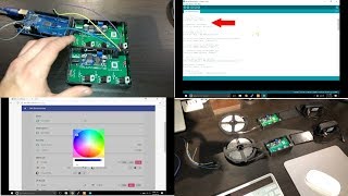

Arduino IDE not set up? Your ESP8266 code won't compile
41sThis troubleshooting rant hits a common pain point and gives a direct fix, sparking comments from frustrated makers.
▶ Play Clip"Exactly what it promises: a genuinely complete, Windows-specific guide with no bait-and-switch."
Matt from MKSmartHouse demonstrates how to set up the software for an ESP8266-based LED Strip Control device on Windows. The complete workflow covers wiring an Arduino for firmware flashing, configuring the firmware with WiFi and MQTT settings, uploading it to multiple strips, testing via MQTT.fx, and finally integrating the strips into OpenHAB with items, sitemaps, and rules.
Matt explains how to set up LED Strip Control software on Windows for OpenHAB. You can connect 2 or more LED strips by simply repeating the steps, and users are directed to the website for ready-to-copy commands.
You need an Arduino UNO or MEGA with USB cable plus male-to-male Dupont jumper cables. Links are provided in the video description and website.
Place a jumper cable from RES to GND on the Arduino, then connect the LED Strip Control pins: TX to TX, RX to RX, GND to GND, and 3.3V to 3.3V. Verify the 2-pin jumper is above PGM.
Download the LED Strip Control firmware from Matt's website, extract the ZIP file, and open the code in Arduino IDE. The exact page link is in the description.
Change only the values inside quotation marks for SSID and password. The ESP8266 only supports 2.4GHz WiFi, so do not use 5GHz credentials.
Set the hostname, update path, and the username/password used to protect the device's built-in web interface. Usually only the last digit of the hostname changes.
Set the subscribeTopic, MQTT server IP address, and unique device ID. Changing the last digit of the device ID differentiates each device on the MQTT broker.
In Arduino IDE select Board 'Generic ESP8266 Module' and the correct COM port. Click upload and wait for the output to show '100%' and 'Done uploading'.
Unplug the first strip, make sure the jumper is over PGM on the second strip, reconnect the Dupont wires, then change the hostname number and unique device ID before uploading the same firmware.
Open MQTT.fx, subscribe to '#' to see all traffic, then publish '100;100;100;' to each strip's subscribeTopic to verify that both strips change color.
In /etc/openhab2/items/home.items, create Group, Color, and String items for each LED strip. The String item carries the MQTT subscribeTopic at the end.
In /etc/openhab2/sitemaps/home.sitemap, add Colorpicker entries like 'Colorpicker item=MKLEDStripControl1Color' inside the MK-Room frame.
In /etc/openhab2/rules/home.rules, write rules that capture HSB values from the color picker, split them into RGB, build 'R;G;B;' MQTT messages, and send them to the device subscribeTopic.
In OpenHAB Basic UI, UP turns the strip on, DOWN turns it off, and the circle opens a color picker. Final physical installation is covered in the next video.
After this Windows walkthrough, you have fully flashed, MQTT-tested LED strips that are controllable through OpenHAB's color picker. The next step is to install the device in its final location.
What WiFi band does the ESP8266 require?
2.4 GHz only.
02:39
Which pins on the LED Strip Control connect to the Arduino?
TX to TX, RX to RX, GND to GND, and 3.3V to 3.3V.
01:32
What must be set above PGM on the LED Strip Control?
The 2-pin jumper must be above PGM.
01:44
What three MQTT settings must be configured in the firmware?
Subscribe topic, MQTT server IP address, and unique device ID.
03:52
How do you test a strip's color change in MQTT.fx?
Publish '100;100;100;' to the strip's subscribeTopic.
05:49
What three item types are created per LED strip in OpenHAB?
Group item, Color item, and String item.
06:52
How do you differentiate multiple devices on MQTT?
Change the last digit of the unique device ID and hostname for each device.
04:04
What does the OpenHAB rule do with the colorpicker data?
It converts HSB values to RGB values and sends them as 'R;G;B;' MQTT messages to the device.
08:06
Flashing requires a simple pin bridge
A small jumper from RES to GND puts the ESP8266 into programming mode — a handy hardware trick that avoids a USB-to-serial adapter.
01:20ESP8266 is 2.4GHz-only
A common pitfall that causes connectivity failures for users with dual-band WiFi routers.
02:39One firmware, per-device MQTT identity
Changing only the device ID and hostname lets the same firmware run on many strips with minimal effort.
03:40OpenHAB items mirror MQTT topics
Group, Color, and String items create a clean bridge between the OpenHAB user interface and MQTT commands.
06:08Rules translate UI colors to MQTT protocol
The HSB-to-RGB conversion rule is the core piece that makes the color picker drive the actual hardware over MQTT.
08:06[00:00] Hey guys Matt here from MKSmartHouse.com and in this video I am going to show you how to setup the software for the LED Strip Control using Windows. So in the last video we left off with the LED Strip Control Device being fully built
[00:21] so all it needs is firmware and to be connected to the home automation server. Many of you have been asking what to do if you were to connect more than 1 of any of So in this video I am going to show you how to connect 2 LED Strips to openhab, you can
[00:37] repeat the steps for the second one to add even 20 LED Strips. I recommend having my website open up so that way you have all the steps and commands ready, and so you do not have to type in everything you can just copy and paste.
[00:52] I know this is the software video but, there are some hardware things that we need besides We are going to need an arduino of some kind preferably a UNO or a MEGA equivalent with
[01:04] its usb cable of course and male to male dupont jumper cables. Links to these items will be in the description or on the website. On my website you will also find my shop where you can find the kit, and pcb to make this
[01:20] The first thing we are going to do is grab the arduino and put a jumper cable from RES Then grab the LED Strip Control and connect all the pins to their corresponding spots
[01:32] so, TX to TX, RX to RX, GND to GND, and 3.3V to 3.3V. Before we continue, check to make sure the 2 pin jumper is above PGM.
[01:44] Please note that in this video I will not go over how to setup the arduino IDE and will assume that it is set up and you know how to connect an arduino to it. If you do not know how to set it up or it is not setup then go check out my Door sensor
[01:58] software video where I go in detail of the entire process. Recently people have been telling me that they cannot compile the arduino code I have That is because your Arduino IDE is not setup, so if you are having this issue please go
[02:12] watch my door sensor software video I show exactly how to set it up. Next we are going to head over to my site, the link is in the description to the exact page and press the download LED Strip Control Firmware.
[02:25] On the new page press download.Then go to your file explorer and downloads folder and A pop up will come up asking if you want to put it in a folder, click OK.
[02:39] It should bring up the code for the LED Strip Control, and there are only a few things we The first thing is the wifi settings which are the ssid and password so change those Please keep in mind that the esp8266 only works on 2.4ghz so type in your 2.4ghz wifi
[02:59] ssid and password not your 5ghz. Also when adding the information only change what is inside the quotation marks. Next set of parameters are the Web Updater settings.
[03:11] The devices I designed are great because I implemented a web user interface for each individual device so that way if you ever have to flash new firmware you just go to The web address information is found at that top of the code in the giant comment block.
[03:27] The first parameter is the hostname of the device, usually I only change the last digit but since this is the first LED Strip Control I will keep it as it is. Next is the update path and personally I don’t change that.
[03:40] After that is the web user interface username and password, these are the credentials you use to access the webpage because each device is protected. The next set of parameters are for mqtt.
[03:52] The first one is the subscribeTopic and this is the topic for which the device listens The next one is the MQTT Server Ip address and this is simply the IP address of your
[04:04] The last one is the Unique device ID and this simply differentiates each device on the MQTT side, I usually just change the last digit for every single device.
[04:16] 12. So go to tools and make sure the Board: is Generic ESP8266 Module and the port is COM Once those are good press the upload button, it is the one with an arrow pointing to the
[04:32] When it is uploading you should see dots moving at the bottom and some percents. After it is done uploading you should see it say 100% and Done uploading. Great now unplug the Arduino and the dupont wires from the first LED Strip and make sure
[04:48] the jumper is over PGM on the second LED Strip and connect the dupont wires to their corresponding Now let's make some changes for the second LED Strip so connect the arduino again.
[05:01] First change the number in the host from a 1 to a 2. Lastly, increment the device ID. Now upload the code the same way you did the first one.
[05:15] Once it finished uploading unplug the arduino as well as the dupont wires. 17. To confirm that it flashed correctly and is working you can fire up MQTT.fx, connect to
[05:31] the server and in the subscribe section type in # and press subscribe. If you do not have MQTT.fx then check out my Home Automation Server Setup Guide. In the topic bar type in the subscribeTopic that we wrote in the first LED Strip Control
[05:49] Next in the message box type in 100;100;100; and press publish. In the topic bar type in the subscribeTopic that we wrote in the second LED Strip control
[06:08] This LED Strip should have also changed color. Now the devices are complete and just need to be added to OpenHAB. The first thing we are going to do is create the LED Strip Control items.
[06:23] So type in sudo nano /etc/openhab2/items/home.items and press enter, you may need to type in admin password. //LED Strip Control Group MKLEDStripControl1Group "Desk LED Strip"
[06:37] (All) Color MKLEDStripControl2Color "Cubes LED Strip" Now let me go over the items we created. Each LED Strip has 3 Items that go along with it.
[06:52] The first item is a group item and what this does is group all the items for the LED Strip The next item is a color item and it is the item that deals with your interaction with the user interface, this is the item we will use in the sitemap file.
[07:08] The last item is a string item and this is the item where the MQTT command will be sent to, as you can see the subscribeTopic is at the end. Now press control x then y and enter.
[07:22] 26. Type in sudo nano /etc/openhab2/sitemaps/home.sitemap and press enter. If you are following along with my series then we have many different frames in our
[07:38] I am going to put the device in the frame called MK-Room. So go to the frame and type in: Colorpicker item=MKLEDStripControl1Color Colorpicker item=MKLEDStripControl2Color and press enter, what we did is import the
[07:53] item into the sitemap so we can control it from the user interface in the form of a color Now press control x then y and enter. There is one more thing we have to do and that is make a rule where it will convert
[08:06] the color picker into MQTT the device can understand. In ssh type in sudo nano /etc/openhab2/rules/home.rules and press enter.
[08:20] var int blueValue var String RGBvalues In the bottom of the file type in: rule "MKLEDStripControl1" greenValue = hsbValue.green.intValue blueValue = hsbValue.blue.intValue
[08:32] rule "MKLEDStripControl2" when blueValue = hsbValue.blue.intValue RGBvalues= redValue.toString + ";" + greenValue.toString the colorpicker and send them through MQTT. 29.
[08:44] and then Basic UI. If you press the UP button it turns the LED strip on, If you press the DOWN button it turns the LED Strip off, and if you press the circle it brings up a color picker and
[09:00] The software is complete, now all we have to do is install the device in its final place which will be completed in the next final installation video.
[09:12] section below or head over to mksmarthouse.com/forum. Good Bye!

⚡ Saved you 0h 09m reading this? Transcribe any YouTube video for free — no signup needed.