
Satisfying LED Light Show for This Sports Sign
54sMesmerizing DIY LED effects are perfect for satisfying video loops and grabbing attention.
▶ Play Clip"Delivers exactly what the title promises: a full DIY build, wiring, software setup, and voice-control demo for a WiFi LED sports sign."
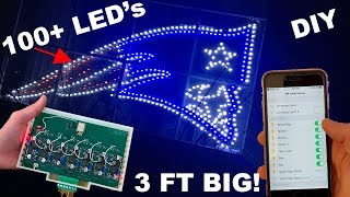
Matt from MK Transcom built a large WiFi-controlled LED New England Patriots sign with animated light shows and voice control via Alexa, Google Home, Siri, Home Assistant, and OpenHAB. The video walks through the hardware construction, the electronics in the control box, and the software setup for flashing and smart-home integration.
Built a New England Patriots sign with individually addressable LED zones, controlled by phone, Amazon Echo, Google Home, and smart-home hubs.
The 'border' effect keeps the middle LEDs stationary while a snake-like animation travels around the border; speed is adjustable.
The 'follow' effect sweeps through each zone from the three border zones to the face, blue, and red sections; a 'both' mode runs border and follow simultaneously.
The sign face is stainless steel, laser cut from a DXF file exported from CAD software; each LED has its own hole.
A single detachable cable connects the sign to a 3D-printed control box powered by a 16V laptop power supply.
Seven buck converters provide a separate voltage for each LED zone because red LEDs need only 2.2V while white LEDs need more.
Enable pins from each buck converter go to an ESP8266, which switches zones on and off; a bridged transistor fixed an initial design flaw.
After flashing a prebuilt bin file via serial, the device connects to WiFi, publishes MQTT, and is integrated into Home Assistant/OpenHAB for Alexa, Google Home, and Siri control.
This project shows how combining laser-cut fabrication, modular power electronics, and open-source home automation can turn a static sign into an interactive, voice-controlled light show.
Which two open-source home automation platforms can control this LED sign?
Home Assistant and OpenHAB.
02:31
What file format was used for laser cutting the steel sign face?
DXF.
03:58
What voltage is the laptop power supply used for the sign?
16 volts.
04:55
How many buck converters are in the control box and why?
Seven; each LED zone gets its own voltage because different colors draw different amounts of power.
06:07
What voltage is set for the red LEDs?
2.2 volts.
06:23
Which microcontroller handles WiFi control in the sign?
ESP8266.
07:04
How was the faulty transistor circuit fixed?
He bridged the transistor with solder so the enable pin connects directly to the ESP.
08:28
What is the 'border' effect?
The middle LEDs stay stationary while a snake-like animation moves around the border.
01:09
What is the recommended way to set buck converter voltages before connecting the ESP?
Use alligator wires and a multimeter to set each converter to the desired voltage before plugging in the jumper.
10:04
What prerequisite is needed in Home Assistant for the sign config?
MQTT must be installed.
10:46
Voice-controlled custom LED sign
Shows how a DIY sign can be integrated with Alexa, Google Home, Siri, and smart-home hubs rather than being a standalone gadget.
00:41Laser-cut steel from CAD design
Using a DXF file for laser cutting gives precise LED holes and a clean, professional finish.
03:45Per-channel buck converters for LED voltages
A separate buck converter per color zone ensures each LED type gets the right voltage, avoiding under- or overdriving.
06:07Set voltages before connecting the ESP
A practical safety step: set the 5V buck converter before inserting the power jumper to avoid damaging the board.
09:50[00:01] society Matt here from MK Transcom and in this video I'm gonna show you how I in this video I'm gonna show you how I made my sport sign so those of you not
[00:26] from America we have this thing called the Super Bowl where are the two best NFL teams from the AFC and NFC Division face-off and this year it is or this season it is the New England Patriots versus the Rams and me personally I am a
[00:41] New England Patriots fan so I made this sign about a couple years maybe one or two years ago but this was the year that I finally made a Wi-Fi controlled my phone as well as the Amazon echo Google home and all those good smart
[00:56] home devices and home assistant so this right here is the New England Patriots logo so first let me give you a demo of everything that they can do so this right here is called the border effect and so it has all the middle LEDs
[01:09] stationary and then it just goes around and sort of like a snake fashion around the sign and then there's another effect which I like to call follow which it goes through each of the LEDs it starts off with the three border zones and then
[01:24] it goes to the face then the blue part and then the red part the last effect is where it does both it does the border and the follow at once this one is my personal favorite and I can adjust the speed however I want so I can make it
[01:38] speed however I want so I can make it really fast or slow it down and make it very slow I'll show you guys the controls in a bit but not only do you have effects but you can also set it to none and you can just have the entire
[01:50] sign a lit up at once or you can individually control each individual zone and now let me show you that it can be controlled from Alexa Alexa turn on be controlled from Alexa Alexa turn on Sport sign and there you go she turned
[02:04] on the sport sign and it can also be controlled from Google home and Siri now let me show you guys all the controls from the software side alright so here here are the individual controls this is from
[02:16] assistant actually let me show you guys home assistant really quickly BAM there it is and if we scroll down we have all the and if we scroll down we have all the different things for the sign so it's
[02:31] exactly the same thing from openhab and home assistant so since we're in home assistant let's just do it from here so I can turn off let's turn off the entire sign you can turn off the entire sign turn on the sign well let's turn it off
[02:46] and then you have all the individual ones so this is border 3 border to ones so this is border 3 border to border 1 red and then we have the face plus the star and we have the blue and then if you turn on the effects you can
[03:03] select the effect from here and then we can do border and I'll do the border you can do border and I'll do the border you can do follow and then we can do both and then using the brightness slider you can adjust the speed there you go it's
[03:17] going a little bit crazy over there now I have noticed that from the cameras angle it looks kind of exposed it looks a lot better in real life and so now let's get rid of the effect and set it to none let's just turn on the sport
[03:31] alright now that we've gone over controls and again it is the same thing in openhab there you go except an open have you just have a thing that says effects right here and your slider is right here but we'll talk about how to
[03:45] get it into openhab and home assistant later now let's go ahead and take a tour how it works so the actual sine part of it is made on so the actual sine part of it is made on stainless steel and so I had this laser
[03:58] cut so it cut each individual hole for all the LEDs I designed it in CAD software and then export it as a DXF file and had it cut out so the leds were manually put into each slot we'll look at the back later but
[04:14] from the front you can just see just the LEDs and the LEDs were pushed in from the back alright so this is the back of the sign as you can see we have all of the LEDs run we have on the border side every three LEDs is connected so
[04:30] that way we have that cool effect then all the blue LEDs are connected and they're all just simply pushed in there's no hot glue so only friction is there's no hot glue so only friction is keeping it in place just taking a tour
[04:43] each one of these were soldered together and then we have one gray cable that's coming from the sign and then from the sign it it goes into the control box
[04:55] right here and so there's just one connector this connector is detachable so you can remove it and it is all being powered by this power supply from an old laptop and this is a 16 volt power supply so let's go ahead and take a tour
[05:10] inside the box and let me show you all the components that it's using so this is a 3d printed enclosure I designed you have vents on both sides of it and then on the bottom there's nothing you have the port for the sign and then you have
[05:25] your input ports for the power but let's go ahead and open up and take a look so the top cover was only held in by two screws over here and then you can just simply lift this up and slide it forward and here we have all of the electronics
[05:39] that's controlling the side over here we have the input and you can detach the have the input and you can detach the sign from the PCB there we go it's just a seven pin connector and it's a terminal block so that way you just
[05:52] plug it in the reason I have it on another PCB underneath here is because I accidentally chose when I was designing in the PCB I chose the wrong terminal block or a terminal connector and then over here we have the power this is an
[06:07] edge a ste connector and then we have seven buck converters and so the reason I have different buck converters for each individual channel is because each led draws a different amount of voltage so in order to do that I have individual
[06:23] buck converters away I can choose the exact voltage for each LED so for example the red LEDs they use a lot less power than the white LEDs so this is at 2.2 volts so another thing that I kind of messed up on the PCB design is I was
[06:36] of messed up on the PCB design is I was going to use a more complex circuit not a different way to controlling you but that didn't end up working shout out to the people on my discord I think it was Zbot he helped me out and a bunch of
[06:51] people on my discord so if you guys are not on the discord jump on there's a link in the description below also shout out to the people on reddit that helped out and so then I had an enable pin coming from each buck converter and that
[07:04] coming from each buck converter and that goes directly to the esp8266 that's why bypasses these little circuits I just bridged the transistor so that way the to the 16 volts and then you just turn on and off the buck converters so that's
[07:20] going to the ESP also when I was designing the PS the PCB I forgot to include a ground for the ESP so I manually took a wire and did the ESP
[07:32] first time and then you have your programming headers you have your header that chooses if you're in run or program mode then you have your 5 volt to 3.3 volt converter you have your power pin so
[07:44] converter you have your power pin so this is how you choose to turn on and off of the ESP so that way when you're programming you're not feeding voltage buck converter powers the ESP it converts the 16 volts to the 5 volts and
[07:58] then the 5 volts of 3.3 volts and then these are for the sign itself and that's it for the electronics part here is another PCB and I got this PCB from PCB way PCB way is a company that specializes in PCB prototyping PCB
[08:14] assembly and SMD cental in this video we will be using a PCB that was made by PCB white as you can see the PCB is high quality and very nicely made if you use the cash code on the screen you can get $5.00 on PCB way you're gonna do this
[08:28] transistor and then I was gonna use these resistors for voltage dividers but want to know more about why it didn't work then check it out on the discord I luckily it was a simple fix I just bridged the transistor so I put
[08:44] solder on all of this and then I directly connected the enable pin to this right here which goes directly to the ESP so this is the front of the PCB and here is the back I didn't any components on the back everything
[08:56] fit nicely on the front as you can see here and then inside the enclosure it's just held down by four screws all right now that I talked about the hardware let's get into the software all right so now let's talk about how I did the
[09:08] software part of this I won't be going into too much detail because I figured can pretty much figure out the software and it's pretty much the same thing that first thing you would have to do is get the bin file from my website connected
[09:22] the bin file from my website connected the arduino using the TX TX pins you just have to match them up to the device so you just match TX to TX Rx arts ground the ground and 5 volts of 5 volts make sure the programming pin is in
[09:35] program mode then flush the bin file onto the device using PI flasher once that's done you put the jumper back into run mode I would like to make one more note and that is after you program it make sure you don't put in the jumper
[09:50] for the power make sure that's disconnected set the voltage first on the buck converter to 5 volts this one that is going to the 5 volt for 3.3 volt converter make sure that's set to 5 volts first and then you can put in the
[10:04] jumper to control this also before you plug in anything into this side make sure you set all of your buck converters to that your desire to voltages beforehand and you can simply do this by using alligator wires and a multimeter
[10:18] you open up you plug it into the wall you open up settings on your phone then you go to Wi-Fi connect to the Wi-Fi network of the device and type in your credentials for your Wi-Fi you're MQTT server and your web update our page once
[10:34] that's on you press save and then we get into connecting it to either a homeless into connecting it to either a homeless system or openhab so this is on the screen the home assistant config that you put in your configuration file
[10:46] you will need to have MQTT installed already but here it is on the screen now it'll also be in the description below as well as on my website and then for open hub you just need to put this in your items file also in the description
[11:00] below and then you need to put this in your sitemap file and then in terms of how I connect control this from Amazon I and from Google home as well as Siri all I did was do the respected things on open abre home assistant server example
[11:16] and open hub I put in the switchable tags for the switches to control all the individual things now as many of you noticed I didn't go into too much detail that's because I figured that most of you won't be making this this is just
[11:30] the video we're sharing what I did and also some ideas for you so if you had it sports team that you really liked you can also do the same thing and there's a just general concept for you to look at and understand and just give you ideas
[11:43] overall and if you have any questions obviously in the comment section below join the discord you can ask me questions on there ask other people there yeah or even on the forum okay so our second forum but just because I love
[11:56] this sign so much let me show you guys the effects and everything it can do all over again so the first thing is you can turn on and off all the LEDs and you can turn on each individual set of LEDs and then lastly we have the border effect
[12:13] where it moves around the border then you have the following fact where it you have the following fact where it jumps from the different zones and then follow and the border this one's my personal favorite because I think it's
[12:27] more like flashy and I just love how it works especially if you speed it up like video enjoyable or helpful at all smash that like button if you're smarming enthusiast like me then press that subscribe button alright if you have any
[12:41] questions in the comment section below or head over to em kitchen marcom slash forum or head on over to the discord where we have a nice community going there and I want to expand it more well than that see you guys in the next video

⚡ Saved you 0h 13m reading this? Transcribe any YouTube video for free — no signup needed.